Strive for perfection in your projects using AD5142A and PIC32MZ2048EFM100
Say goodbye to analog limitations

Published Nov 10, 2023
Click board™
DIGI POT 12 Click
Dev. board
Curiosity PIC32 MZ EF
Compiler
NECTO Studio
MCU
PIC32MZ2048EFM100
Maximize the potential of your electronic circuits by unlocking unparalleled precision with our digital potentiometer – the key to achieving peak performance and efficiency in every application.
A
A
Hardware Overview
How does it work?
DIGI POT 12 Click is based on the AD5142A, a dual-channel, 256-position nonvolatile digital potentiometer from Analog Devices. The resistor wiper position is determined by the RDAC register contents, which act as a scratchpad register, allowing unlimited changes of resistance settings. The scratchpad register can be programmed with any position setting using the standard I2C interface by loading the 16-bit data word. The nominal resistance of the RDAC between terminals A and terminals B (RAB) is 10KΩ with 8-bit RDAC latch data decoded to select one of the 256 possible wiper settings. When a desired position is found, this value can be stored in the onboard EEPROM memory; thus, the wiper position is always restored for subsequent power-ups. The EEPROM data can be read back, written
independently, and protected by software. This Click board™ communicates with MCU through a standard 2-Wire I2C interface and operates at Standard (100KHz) and Fast (400KHz) data transfer modes. The I2C address can be selected via the ADDR SEL jumpers with 0 selected by default. There is an RST pin for resetting the digital potentiometers RDAC registers from EEPROM, with active LOW logic. In addition, this Click board™ comes with the INDEP SEL jumper that allows you to choose between the potentiometer and the linear gain setting mode, with the potentiometer mode set by default (0). The linear gain setting mode of operation can control the potentiometer as two independent rheostats connected at a single point. Once the jumper is set, it can not be turned off by software. In
addition, there is a burst mode in which multiple data bytes can be sent to the host MCU. The Shutdown mode places the RDAC in a zero power consumption while the data in EEPROM remains. There is no polarity constraint between the B, W, and A on both terminals, but they can not be higher than the VCC (5V maximum) nor lower than the VSS (0V). This Click board™ can operate with either 3.3V or 5V logic voltage levels selected via the VCC SEL jumper. This way, both 3.3V and 5V capable MCUs can use the communication lines properly. Also, this Click board™ comes equipped with a library containing easy-to-use functions and an example code that can be used as a reference for further development.

Features overview
Development board
Curiosity PIC32 MZ EF development board is a fully integrated 32-bit development platform featuring the high-performance PIC32MZ EF Series (PIC32MZ2048EFM) that has a 2MB Flash, 512KB RAM, integrated FPU, Crypto accelerator, and excellent connectivity options. It includes an integrated programmer and debugger, requiring no additional hardware. Users can expand
functionality through MIKROE mikroBUS™ Click™ adapter boards, add Ethernet connectivity with the Microchip PHY daughter board, add WiFi connectivity capability using the Microchip expansions boards, and add audio input and output capability with Microchip audio daughter boards. These boards are fully integrated into PIC32’s powerful software framework, MPLAB Harmony,
which provides a flexible and modular interface to application development a rich set of inter-operable software stacks (TCP-IP, USB), and easy-to-use features. The Curiosity PIC32 MZ EF development board offers expansion capabilities making it an excellent choice for a rapid prototyping board in Connectivity, IOT, and general-purpose applications.

Microcontroller Overview
MCU Card / MCU

Architecture
PIC32
MCU Memory (KB)
2048
Silicon Vendor
Microchip
Pin count
100
RAM (Bytes)
524288
Used MCU Pins
mikroBUS™ mapper
Take a closer look
Click board™ Schematic

Step by step
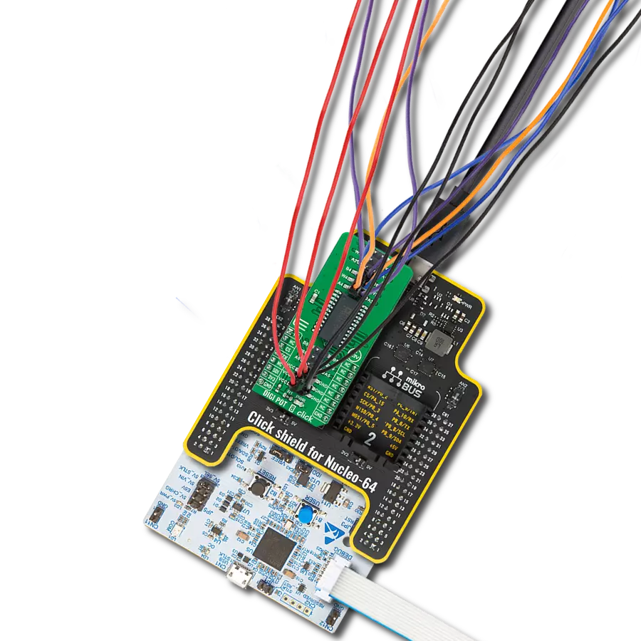
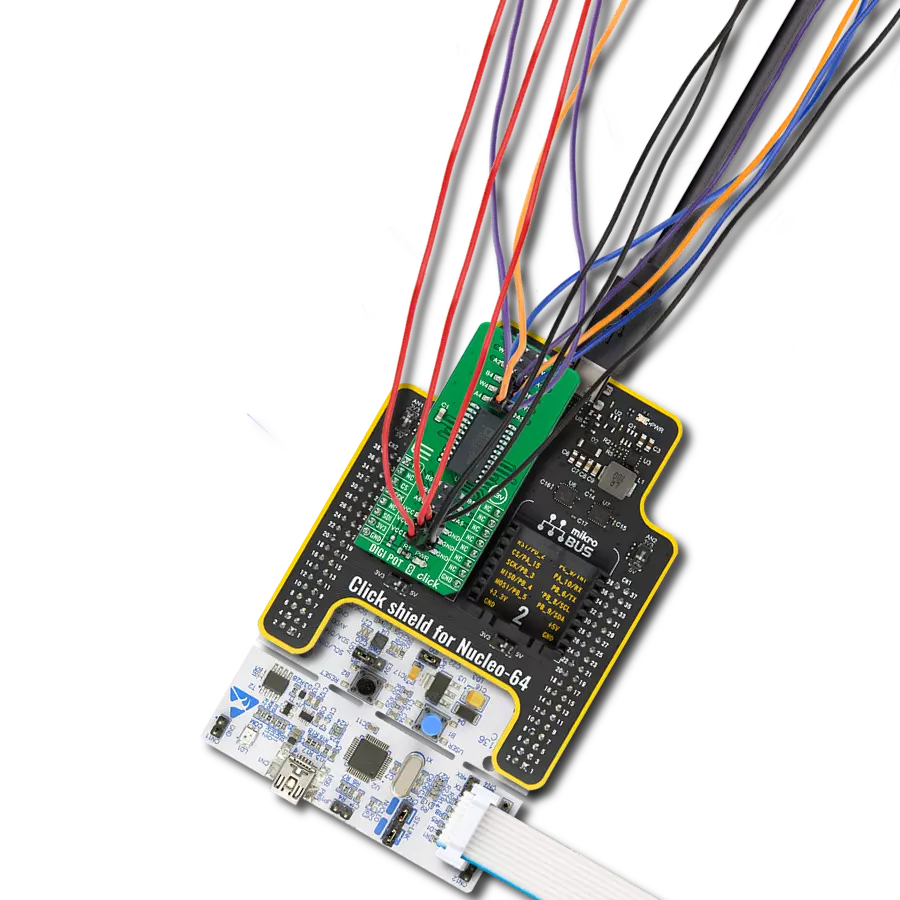
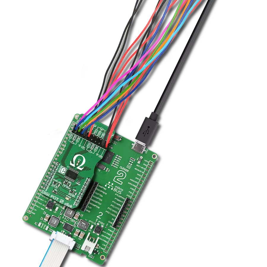
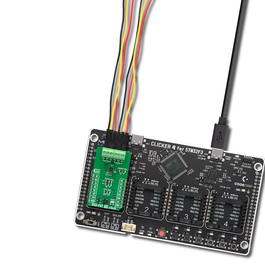
Project assembly

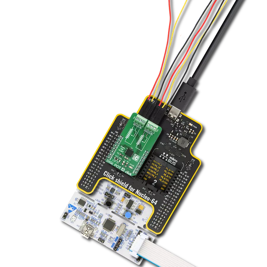
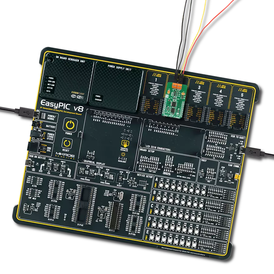
Start by selecting your development board and Click board™. Begin with the Curiosity PIC32 MZ EF as your development board.


Software Support
Library Description
This library contains API for DIGI POT 12 Click driver.
Key functions:
digipot12_set_resistance- DIGI POT 12 set the resistance function.digipot12_get_resistance- DIGI POT 12 get the resistance function.
Open Source
Code example
The complete application code and a ready-to-use project are available through the NECTO Studio Package Manager for direct installation in the NECTO Studio. The application code can also be found on the MIKROE GitHub account.
/*!
 * @file main.c
 * @brief DIGI POT 12 Click example
 *
 * # Description
 * This library contains API for DIGI POT 12 Click driver.
 * The demo application uses a digital potentiometer
 * to change the resistance values of both channels.
 *
 * The demo application is composed of two sections :
 *
 * ## Application Init
 * The initialization of I2C module, log UART, and additional pins.
 * After the driver init, the app executes a default configuration.
 *
 * ## Application Task
 * This example demonstrates the use of the DIGI POT 12 Click board™.
 * The demo application iterates through the entire wiper range and
 * sets the resistance of both channels in steps of approximately 1kOhm.
 * Results are being sent to the UART Terminal, where you can track their changes.
 *
 * @author Nenad Filipovic
 *
 */

#include "board.h"
#include "log.h"
#include "digipot12.h"

static digipot12_t digipot12;
static log_t logger;

void application_init ( void )
{
    log_cfg_t log_cfg;  /**< Logger config object. */
    digipot12_cfg_t digipot12_cfg;  /**< Click config object. */

    /**
     * Logger initialization.
     * Default baud rate: 115200
     * Default log level: LOG_LEVEL_DEBUG
     * @note If USB_UART_RX and USB_UART_TX
     * are defined as HAL_PIN_NC, you will
     * need to define them manually for log to work.
     * See @b LOG_MAP_USB_UART macro definition for detailed explanation.
     */
    LOG_MAP_USB_UART( log_cfg );
    log_init( &logger, &log_cfg );
    log_info( &logger, " Application Init " );

    // Click initialization.
    digipot12_cfg_setup( &digipot12_cfg );
    DIGIPOT12_MAP_MIKROBUS( digipot12_cfg, MIKROBUS_1 );
    if ( I2C_MASTER_ERROR == digipot12_init( &digipot12, &digipot12_cfg ) )
    {
        log_error( &logger, " Communication init." );
        for ( ; ; );
    }

    if ( DIGIPOT12_ERROR == digipot12_default_cfg ( &digipot12 ) )
    {
        log_error( &logger, " Default configuration." );
        for ( ; ; );
    }

    log_info( &logger, " Application Task " );
    log_printf( &logger, " ----------------------------\r\n" );
    Delay_ms ( 100 );
}

void application_task ( void )
{
    static float res_kohm;
    for ( uint8_t n_cnt = DIGIPOT12_RES_0_KOHM; n_cnt <= DIGIPOT12_RES_10_KOHM; n_cnt++ )
    {
        if ( DIGIPOT12_OK == digipot12_set_resistance( &digipot12, DIGIPOT12_WIPER_SEL_1, ( float ) n_cnt ) )
        {
            if ( DIGIPOT12_OK == digipot12_get_resistance( &digipot12, DIGIPOT12_WIPER_SEL_1, &res_kohm ) )
            {
                log_printf( &logger, " Rwb1 : %.2f kOhm\r\n", res_kohm );
                Delay_ms ( 100 );
            }
        }

        if ( DIGIPOT12_OK == digipot12_set_resistance( &digipot12, DIGIPOT12_WIPER_SEL_2, ( float ) ( DIGIPOT12_RES_10_KOHM - n_cnt ) ) )
        {
            if ( DIGIPOT12_OK == digipot12_get_resistance( &digipot12, DIGIPOT12_WIPER_SEL_2, &res_kohm ) )
            {
                log_printf( &logger, " Rwb2 : %.2f kOhm\r\n", res_kohm );
                Delay_ms ( 100 );
            }
        }
        log_printf( &logger, " ----------------------------\r\n" );
        Delay_ms ( 1000 );
        Delay_ms ( 1000 );
        Delay_ms ( 1000 );
        Delay_ms ( 1000 );
        Delay_ms ( 1000 );
    }
}

int main ( void )
{
    /* Do not remove this line or clock might not be set correctly. */
    #ifdef PREINIT_SUPPORTED
    preinit();
    #endif

    application_init( );

    for ( ; ; )
    {
        application_task( );
    }

    return 0;
}

// ------------------------------------------------------------------------ END
Additional Support
Resources
Category:Digital potentiometer