Unlock the power of linear Hall switching using MLX90242 and STM32F031K6
Powerful sensing, unparalleled precision

Published Oct 01, 2024
Click board™
LIN HALL Click
Dev. board
Nucleo 32 with STM32F031K6 MCU
Compiler
NECTO Studio
MCU
STM32F031K6
Empower your design with Linear Hall Switch engineered to provide accurate and proportional output, perfect for applications demanding reliable linear position and current sensing
A
A
Hardware Overview
How does it work?
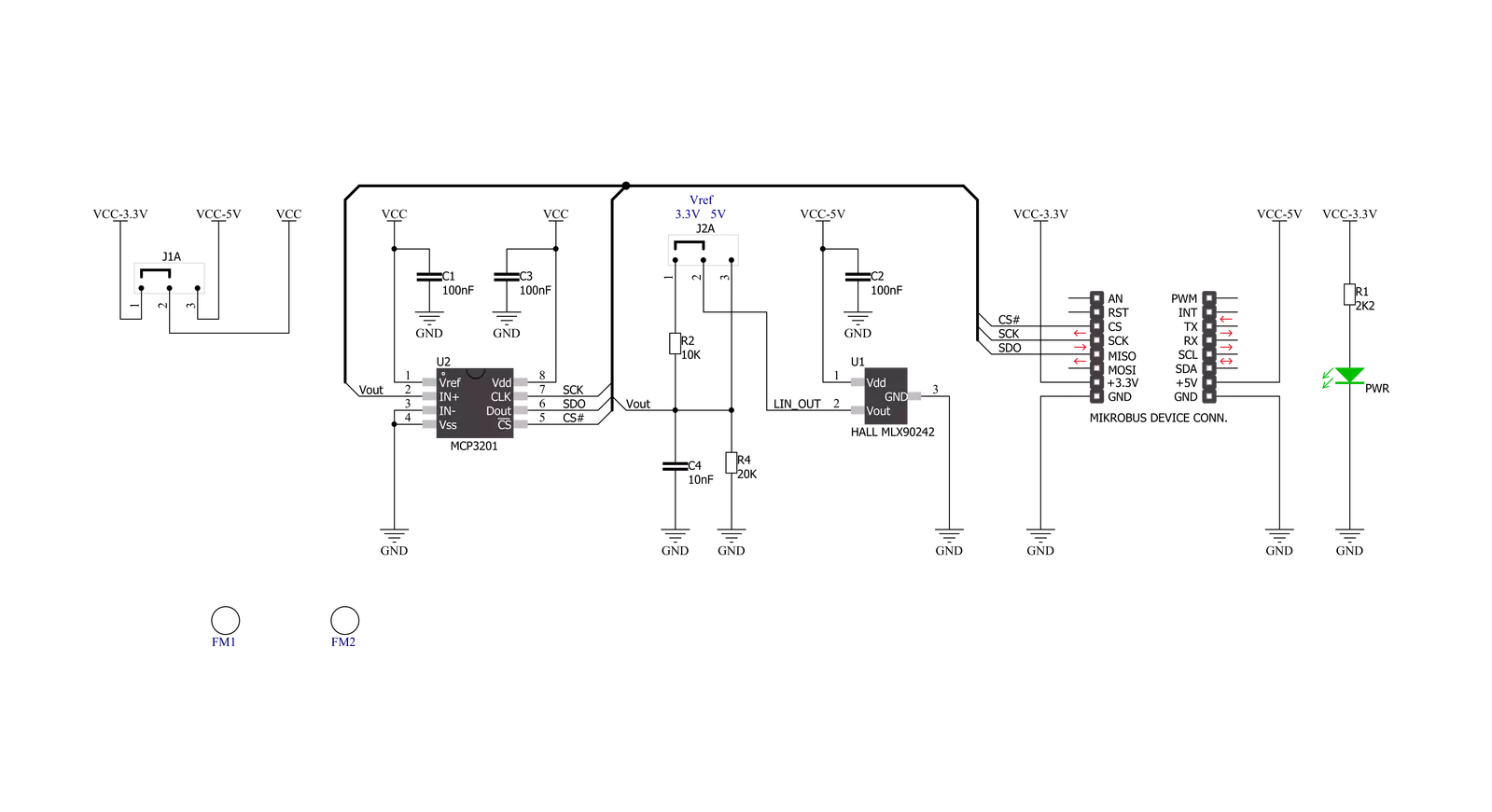
LIN HALL Click is based on the MLX90242, a linear Hall-effect sensor designed in CMOS technology from Melexis Technologies. The MLX90242 features active error correction circuitry (Hall plate quadrature spinning current and chopper-stabilized amplifier), virtually eliminating the offset errors usually associated with Hall-effect devices. It allows using generic magnets, making it suitable for highly accurate rotary and linear position detection in automotive and industrial applications. The ratiometric output voltage of the MLX90242 is proportional to the supply voltage.
For a positive slope, the voltage at the output will increase as a South magnetic field is applied to the branded face of the MLX90242. Conversely, the voltage output will decrease in the presence of a North magnetic field. For a negative slope, the voltage at the output will increase as a North magnetic field is applied to the branded face of the MLX90242. Conversely, the voltage output will decrease in the presence of a South magnetic field. The output signal of the MLX90242 is then converted to a digital value using MCP3201, a successive approximation A/D converter with a
12-bit resolution from Microchip using a 3-wire SPI compatible interface (read-only). This Click board™ can operate with both 3.3V and 5V logic voltage levels selected via the VOLTAGE LEVEL jumper. It should be highlighted that the MLX90242 works exclusively at 5V, where it is necessary to perform appropriate logic voltage level conversion before using MCUs with different logic levels. However, the Click board™ comes equipped with a library containing functions and an example code that can be used, as a reference, for further development.

Features overview
Development board
Nucleo 32 with STM32F031K6 MCU board provides an affordable and flexible platform for experimenting with STM32 microcontrollers in 32-pin packages. Featuring Arduino™ Nano connectivity, it allows easy expansion with specialized shields, while being mbed-enabled for seamless integration with online resources. The
board includes an on-board ST-LINK/V2-1 debugger/programmer, supporting USB reenumeration with three interfaces: Virtual Com port, mass storage, and debug port. It offers a flexible power supply through either USB VBUS or an external source. Additionally, it includes three LEDs (LD1 for USB communication, LD2 for power,
and LD3 as a user LED) and a reset push button. The STM32 Nucleo-32 board is supported by various Integrated Development Environments (IDEs) such as IAR™, Keil®, and GCC-based IDEs like AC6 SW4STM32, making it a versatile tool for developers.

Microcontroller Overview
MCU Card / MCU

Architecture
ARM Cortex-M0
MCU Memory (KB)
32
Silicon Vendor
STMicroelectronics
Pin count
32
RAM (Bytes)
4096
You complete me!
Accessories
Click Shield for Nucleo-32 is the perfect way to expand your development board's functionalities with STM32 Nucleo-32 pinout. The Click Shield for Nucleo-32 provides two mikroBUS™ sockets to add any functionality from our ever-growing range of Click boards™. We are fully stocked with everything, from sensors and WiFi transceivers to motor control and audio amplifiers. The Click Shield for Nucleo-32 is compatible with the STM32 Nucleo-32 board, providing an affordable and flexible way for users to try out new ideas and quickly create prototypes with any STM32 microcontrollers, choosing from the various combinations of performance, power consumption, and features. The STM32 Nucleo-32 boards do not require any separate probe as they integrate the ST-LINK/V2-1 debugger/programmer and come with the STM32 comprehensive software HAL library and various packaged software examples. This development platform provides users with an effortless and common way to combine the STM32 Nucleo-32 footprint compatible board with their favorite Click boards™ in their upcoming projects.

Used MCU Pins
mikroBUS™ mapper
Take a closer look
Click board™ Schematic
Step by step
Project assembly

Start by selecting your development board and Click board™. Begin with the Nucleo 32 with STM32F031K6 MCU as your development board.


Software Support
Library Description
This library contains API for LIN HALL Click driver.
Key functions:
linhall_read_data- Read 12-bit data function
Open Source
Code example
The complete application code and a ready-to-use project are available through the NECTO Studio Package Manager for direct installation in the NECTO Studio. The application code can also be found on the MIKROE GitHub account.
/*!
 * \file
 * \brief LinHall Click example
 *
 * # Description
 * This is a example which demonstrates the use of Lin Hall Click board.
 *
 * The demo application is composed of two sections :
 *
 * ## Application Init
 * Initializes SPI and LOG structures, initialization driver enable's
 * - SPI and start write log.
 *
 * ## Application Task
 * Read 12-bit ADC value from the MCP3201 chip.
 * Results are being sent to the Usart Terminal where you can track their changes.
 * All data logs on usb uart for aproximetly every 100 ms when the ADC value changes.
 *
 * \author MikroE Team
 *
 */
// ------------------------------------------------------------------- INCLUDES

#include "board.h"
#include "log.h"
#include "linhall.h"

// ------------------------------------------------------------------ VARIABLES

static linhall_t linhall;
static log_t logger;

static uint16_t value_adc;
static uint16_t value_adc_old;
static uint16_t sensitivity;

// ------------------------------------------------------ APPLICATION FUNCTIONS

void application_init ( void )
{
    log_cfg_t log_cfg;
    linhall_cfg_t cfg;

    /**
     * Logger initialization.
     * Default baud rate: 115200
     * Default log level: LOG_LEVEL_DEBUG
     * @note If USB_UART_RX and USB_UART_TX
     * are defined as HAL_PIN_NC, you will
     * need to define them manually for log to work.
     * See @b LOG_MAP_USB_UART macro definition for detailed explanation.
     */
    LOG_MAP_USB_UART( log_cfg );
    log_init( &logger, &log_cfg );
    log_info( &logger, "---- Application Init ----" );

    //  Click initialization.

    linhall_cfg_setup( &cfg );
    LINHALL_MAP_MIKROBUS( cfg, MIKROBUS_1 );
    linhall_init( &linhall, &cfg );

    log_printf( &logger, "  Lin Hall Click  \r\n" );
    log_printf( &logger, "------------------\r\n" );
    Delay_ms ( 100 );

    value_adc_old = 0;
    sensitivity = 30;
}

void application_task ( void )
{
    value_adc = linhall_read_data( &linhall );

    if ( ( ( value_adc - value_adc_old ) > sensitivity ) && ( ( value_adc_old - value_adc ) > sensitivity ) )
    {
        log_printf( &logger, "  ADC Value : %d \r\n", value_adc );
        log_printf( &logger, "------------------\r\n" );

        value_adc_old = value_adc;
        Delay_ms ( 100 );
    }
}

int main ( void )
{
    /* Do not remove this line or clock might not be set correctly. */
    #ifdef PREINIT_SUPPORTED
    preinit();
    #endif

    application_init( );

    for ( ; ; )
    {
        application_task( );
    }

    return 0;
}


// ------------------------------------------------------------------------ END
Additional Support
Resources
Category:Magnetic


