Unlock the power of linear Hall switching using MLX90242 and PIC18F45K50
Powerful sensing, unparalleled precision

Published Jun 20, 2023
Click board™
LIN HALL Click
Dev. board
EasyPIC v8
Compiler
NECTO Studio
MCU
PIC18F45K50
Empower your design with Linear Hall Switch engineered to provide accurate and proportional output, perfect for applications demanding reliable linear position and current sensing
A
A
Hardware Overview
How does it work?
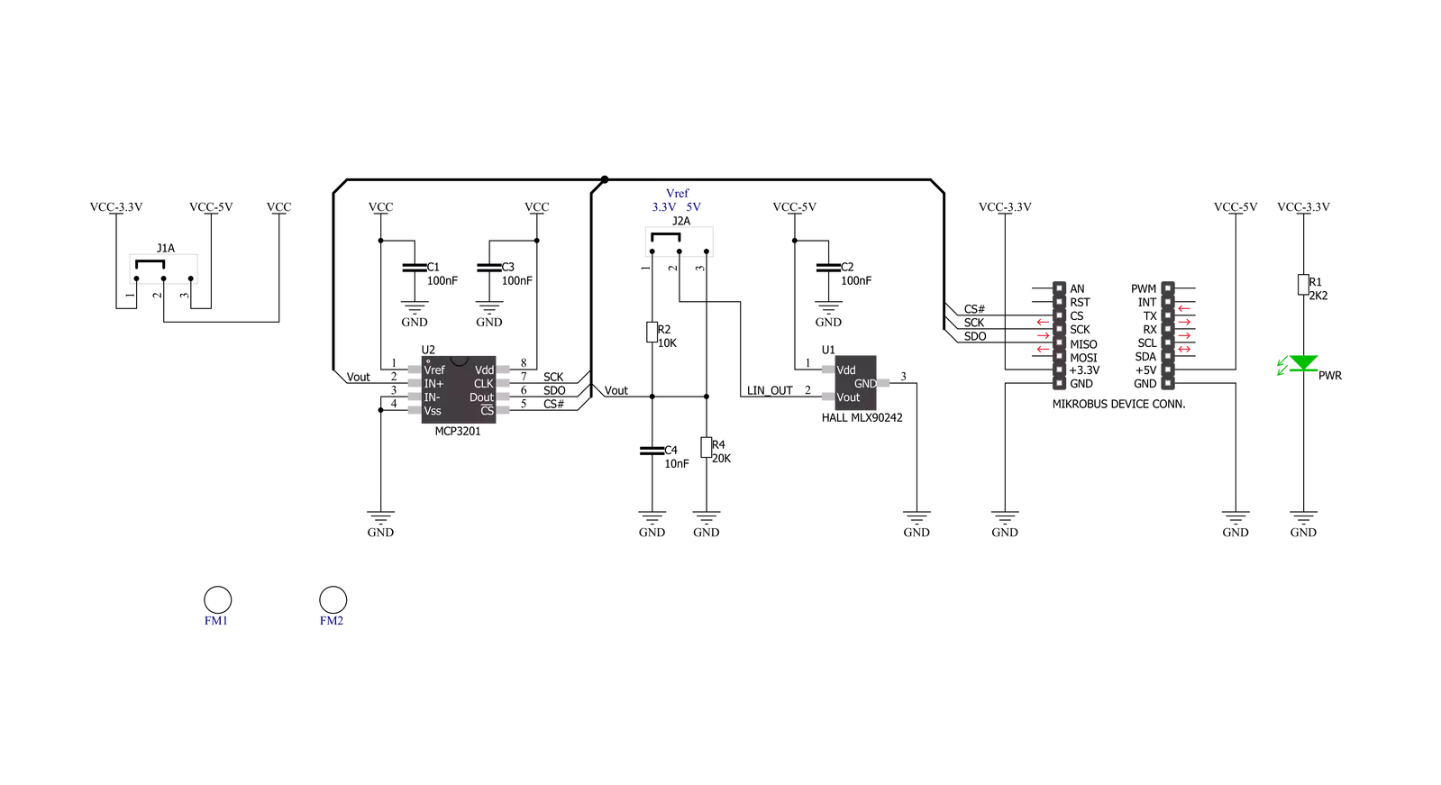
LIN HALL Click is based on the MLX90242, a linear Hall-effect sensor designed in CMOS technology from Melexis Technologies. The MLX90242 features active error correction circuitry (Hall plate quadrature spinning current and chopper-stabilized amplifier), virtually eliminating the offset errors usually associated with Hall-effect devices. It allows using generic magnets, making it suitable for highly accurate rotary and linear position detection in automotive and industrial applications. The ratiometric output voltage of the MLX90242 is proportional to the supply voltage.
For a positive slope, the voltage at the output will increase as a South magnetic field is applied to the branded face of the MLX90242. Conversely, the voltage output will decrease in the presence of a North magnetic field. For a negative slope, the voltage at the output will increase as a North magnetic field is applied to the branded face of the MLX90242. Conversely, the voltage output will decrease in the presence of a South magnetic field. The output signal of the MLX90242 is then converted to a digital value using MCP3201, a successive approximation A/D converter with a
12-bit resolution from Microchip using a 3-wire SPI compatible interface (read-only). This Click board™ can operate with both 3.3V and 5V logic voltage levels selected via the VOLTAGE LEVEL jumper. It should be highlighted that the MLX90242 works exclusively at 5V, where it is necessary to perform appropriate logic voltage level conversion before using MCUs with different logic levels. However, the Click board™ comes equipped with a library containing functions and an example code that can be used, as a reference, for further development.

Features overview
Development board
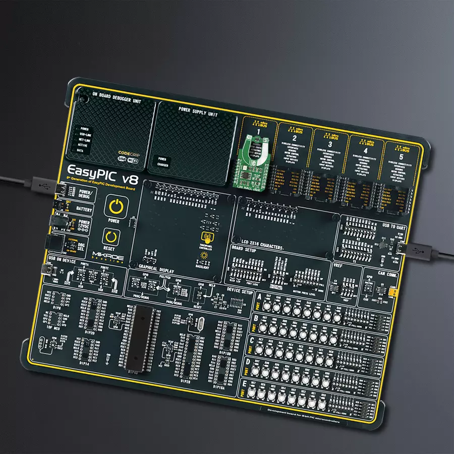
EasyPIC v8 is a development board specially designed for the needs of rapid development of embedded applications. It supports many high pin count 8-bit PIC microcontrollers from Microchip, regardless of their number of pins, and a broad set of unique functions, such as the first-ever embedded debugger/programmer. The development board is well organized and designed so that the end-user has all the necessary elements, such as switches, buttons, indicators, connectors, and others, in one place. Thanks to innovative manufacturing technology, EasyPIC v8 provides a fluid and immersive working experience, allowing access anywhere and under any
circumstances at any time. Each part of the EasyPIC v8 development board contains the components necessary for the most efficient operation of the same board. In addition to the advanced integrated CODEGRIP programmer/debugger module, which offers many valuable programming/debugging options and seamless integration with the Mikroe software environment, the board also includes a clean and regulated power supply module for the development board. It can use a wide range of external power sources, including a battery, an external 12V power supply, and a power source via the USB Type-C (USB-C) connector.
Communication options such as USB-UART, USB DEVICE, and CAN are also included, including the well-established mikroBUS™ standard, two display options (graphical and character-based LCD), and several different DIP sockets. These sockets cover a wide range of 8-bit PIC MCUs, from the smallest PIC MCU devices with only eight up to forty pins. EasyPIC v8 is an integral part of the Mikroe ecosystem for rapid development. Natively supported by Mikroe software tools, it covers many aspects of prototyping and development thanks to a considerable number of different Click boards™ (over a thousand boards), the number of which is growing every day.

Microcontroller Overview
MCU Card / MCU
Architecture
PIC
MCU Memory (KB)
32
Silicon Vendor
Microchip
Pin count
40
RAM (Bytes)
2048
Used MCU Pins
mikroBUS™ mapper
Take a closer look
Click board™ Schematic
Step by step
Project assembly

Start by selecting your development board and Click board™. Begin with the EasyPIC v8 as your development board.


Track your results in real time
Application Output
1. Application Output - In Debug mode, the 'Application Output' window enables real-time data monitoring, offering direct insight into execution results. Ensure proper data display by configuring the environment correctly using the provided tutorial.

2. UART Terminal - Use the UART Terminal to monitor data transmission via a USB to UART converter, allowing direct communication between the Click board™ and your development system. Configure the baud rate and other serial settings according to your project's requirements to ensure proper functionality. For step-by-step setup instructions, refer to the provided tutorial.

3. Plot Output - The Plot feature offers a powerful way to visualize real-time sensor data, enabling trend analysis, debugging, and comparison of multiple data points. To set it up correctly, follow the provided tutorial, which includes a step-by-step example of using the Plot feature to display Click board™ readings. To use the Plot feature in your code, use the function: plot(*insert_graph_name*, variable_name);. This is a general format, and it is up to the user to replace 'insert_graph_name' with the actual graph name and 'variable_name' with the parameter to be displayed.

Software Support
Library Description
This library contains API for LIN HALL Click driver.
Key functions:
linhall_read_data- Read 12-bit data function
Open Source
Code example
The complete application code and a ready-to-use project are available through the NECTO Studio Package Manager for direct installation in the NECTO Studio. The application code can also be found on the MIKROE GitHub account.
/*!
 * \file
 * \brief LinHall Click example
 *
 * # Description
 * This is a example which demonstrates the use of Lin Hall Click board.
 *
 * The demo application is composed of two sections :
 *
 * ## Application Init
 * Initializes SPI and LOG structures, initialization driver enable's
 * - SPI and start write log.
 *
 * ## Application Task
 * Read 12-bit ADC value from the MCP3201 chip.
 * Results are being sent to the Usart Terminal where you can track their changes.
 * All data logs on usb uart for aproximetly every 100 ms when the ADC value changes.
 *
 * \author MikroE Team
 *
 */
// ------------------------------------------------------------------- INCLUDES

#include "board.h"
#include "log.h"
#include "linhall.h"

// ------------------------------------------------------------------ VARIABLES

static linhall_t linhall;
static log_t logger;

static uint16_t value_adc;
static uint16_t value_adc_old;
static uint16_t sensitivity;

// ------------------------------------------------------ APPLICATION FUNCTIONS

void application_init ( void )
{
    log_cfg_t log_cfg;
    linhall_cfg_t cfg;

    /**
     * Logger initialization.
     * Default baud rate: 115200
     * Default log level: LOG_LEVEL_DEBUG
     * @note If USB_UART_RX and USB_UART_TX
     * are defined as HAL_PIN_NC, you will
     * need to define them manually for log to work.
     * See @b LOG_MAP_USB_UART macro definition for detailed explanation.
     */
    LOG_MAP_USB_UART( log_cfg );
    log_init( &logger, &log_cfg );
    log_info( &logger, "---- Application Init ----" );

    //  Click initialization.

    linhall_cfg_setup( &cfg );
    LINHALL_MAP_MIKROBUS( cfg, MIKROBUS_1 );
    linhall_init( &linhall, &cfg );

    log_printf( &logger, "  Lin Hall Click  \r\n" );
    log_printf( &logger, "------------------\r\n" );
    Delay_ms ( 100 );

    value_adc_old = 0;
    sensitivity = 30;
}

void application_task ( void )
{
    value_adc = linhall_read_data( &linhall );

    if ( ( ( value_adc - value_adc_old ) > sensitivity ) && ( ( value_adc_old - value_adc ) > sensitivity ) )
    {
        log_printf( &logger, "  ADC Value : %d \r\n", value_adc );
        log_printf( &logger, "------------------\r\n" );

        value_adc_old = value_adc;
        Delay_ms ( 100 );
    }
}

int main ( void )
{
    /* Do not remove this line or clock might not be set correctly. */
    #ifdef PREINIT_SUPPORTED
    preinit();
    #endif

    application_init( );

    for ( ; ; )
    {
        application_task( );
    }

    return 0;
}


// ------------------------------------------------------------------------ END


