Optimize your electrical control systems with J1031C3VDC and PIC32MZ2048EFM100
Lights, heaters, motors, oh my! SPDTs for all your needs.

Published Oct 18, 2023
Click board™
Relay 4 Click
Dev. board
Curiosity PIC32 MZ EF
Compiler
NECTO Studio
MCU
PIC32MZ2048EFM100
Count on our SPDT relays to seamlessly switch between two different circuits, ensuring your devices operate efficiently and effectively
A
A
Hardware Overview
How does it work?
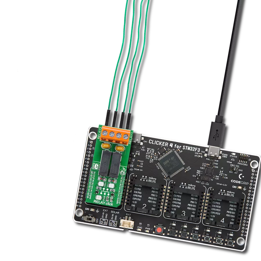
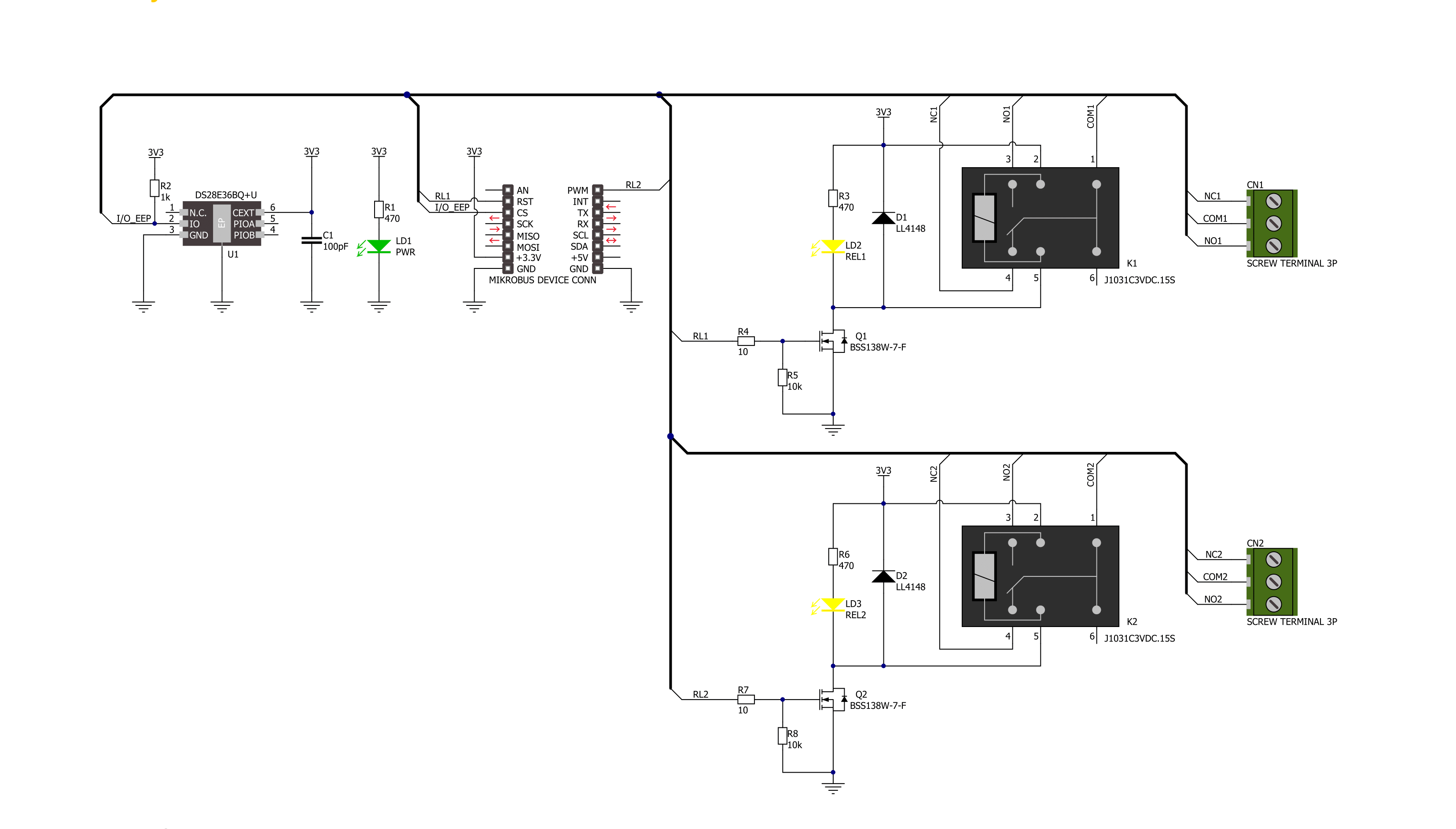
Relay 4 Click is based on dual J1031C3VDC, high-current single-pole double-throw (SPDT) signal relays from CIT Relay and Switch. The J1031C3VDC relay is well known for its reliability and durability, high sensitivity, and low coil power consumption housed in a small package with PC pin mounting. Despite its size (12.5x7.5x10 millimeter (LxWxH)), the J1031C3VDC relay can withstand up to 2A and 125VAC/60VDC maximum. These relays are designed to easily activate their coils by relatively low currents and voltages, making them a perfect choice that any MCU can control. As mentioned, the contact configuration of the J1031C3VDC is a single-pole double-throw (SPDT), meaning it
has one pole and two throws. Based on the default position of the pole, one throw is considered normally open (NO) while the other is normally closed (NC), which is, in this case, its default position. When the coil is energized, it will attract the internal switching elements similar to a switch. This Click board™ uses two mikroBUS™ pins for its proper operation, the RL1 and RL2 pins routed to the RST and PWM pins of the mikroBUS™ socket. These pins control small N-channel MOSFET RET (Resistor Equipped Transistor) transistors that provide enough current for the relay coil. Two resistors are already integrated into the RET, providing the correct biasing and simplifying the
design. Also, each relay has its yellow LED indicator, which signals the state of the relay. When the current flows through the RET, the coil will be energized, and the relay will be switched from a closed to an open switch state. This Click board™ can be operated only with a 3.3V logic voltage level. The board must perform appropriate logic voltage level conversion before using MCUs with different logic levels. Also, it comes equipped with a library containing functions and an example code that can be used as a reference for further development.

Features overview
Development board
Curiosity PIC32 MZ EF development board is a fully integrated 32-bit development platform featuring the high-performance PIC32MZ EF Series (PIC32MZ2048EFM) that has a 2MB Flash, 512KB RAM, integrated FPU, Crypto accelerator, and excellent connectivity options. It includes an integrated programmer and debugger, requiring no additional hardware. Users can expand
functionality through MIKROE mikroBUS™ Click™ adapter boards, add Ethernet connectivity with the Microchip PHY daughter board, add WiFi connectivity capability using the Microchip expansions boards, and add audio input and output capability with Microchip audio daughter boards. These boards are fully integrated into PIC32’s powerful software framework, MPLAB Harmony,
which provides a flexible and modular interface to application development a rich set of inter-operable software stacks (TCP-IP, USB), and easy-to-use features. The Curiosity PIC32 MZ EF development board offers expansion capabilities making it an excellent choice for a rapid prototyping board in Connectivity, IOT, and general-purpose applications.

Microcontroller Overview
MCU Card / MCU

Architecture
PIC32
MCU Memory (KB)
2048
Silicon Vendor
Microchip
Pin count
100
RAM (Bytes)
524288
Used MCU Pins
mikroBUS™ mapper
Take a closer look
Click board™ Schematic
Step by step
Project assembly

Start by selecting your development board and Click board™. Begin with the Curiosity PIC32 MZ EF as your development board.


Software Support
Library Description
This library contains API for Relay 4 Click driver.
Key functions:
relay4_set_relay1_open- This function sets the relay 1 to normally open state by setting the RL1 pin to low logic level.relay4_set_relay1_close- This function sets the relay 1 to normally close state by setting the RL1 pin to high logic level.relay4_set_relay2_open- This function sets the relay 2 to normally open state by setting the RL2 pin to low logic level.
Open Source
Code example
The complete application code and a ready-to-use project are available through the NECTO Studio Package Manager for direct installation in the NECTO Studio. The application code can also be found on the MIKROE GitHub account.
/*!
 * @file main.c
 * @brief Relay 4 Click Example.
 *
 * # Description
 * This example demonstrates the use of Relay 4 Click board by toggling the relays state.
 *
 * The demo application is composed of two sections :
 *
 * ## Application Init
 * Initializes the driver and logger.
 *
 * ## Application Task
 * Switches the relays 1 and 2 state every 5 seconds and displays the state on the USB UART.
 *
 * @author Stefan Filipovic
 *
 */

#include "board.h"
#include "log.h"
#include "relay4.h"

static relay4_t relay4;   /**< Relay 4 Click driver object. */
static log_t logger;    /**< Logger object. */

void application_init ( void )
{
    log_cfg_t log_cfg;  /**< Logger config object. */
    relay4_cfg_t relay4_cfg;  /**< Click config object. */

    /**
     * Logger initialization.
     * Default baud rate: 115200
     * Default log level: LOG_LEVEL_DEBUG
     * @note If USB_UART_RX and USB_UART_TX
     * are defined as HAL_PIN_NC, you will
     * need to define them manually for log to work.
     * See @b LOG_MAP_USB_UART macro definition for detailed explanation.
     */
    LOG_MAP_USB_UART( log_cfg );
    log_init( &logger, &log_cfg );
    log_info( &logger, " Application Init " );

    // Click initialization.
    relay4_cfg_setup( &relay4_cfg );
    RELAY4_MAP_MIKROBUS( relay4_cfg, MIKROBUS_1 );
    if ( DIGITAL_OUT_UNSUPPORTED_PIN == relay4_init( &relay4, &relay4_cfg ) )
    {
        log_error( &logger, " Communication init." );
        for ( ; ; );
    }

    log_info( &logger, " Application Task " );
}

void application_task ( void )
{
    relay4_set_relay1_open ( &relay4 );
    log_printf( &logger, " Relay 1 set to normally open state\r\n" );
    relay4_set_relay2_close ( &relay4 );
    log_printf( &logger, " Relay 2 set to normally close state\r\n\n" );
    Delay_ms ( 1000 );
    Delay_ms ( 1000 );
    Delay_ms ( 1000 );
    Delay_ms ( 1000 );
    Delay_ms ( 1000 );

    relay4_set_relay1_close ( &relay4 );
    log_printf( &logger, " Relay 1 set to normally close state\r\n" );
    relay4_set_relay2_open ( &relay4 );
    log_printf( &logger, " Relay 2 set to normally open state\r\n\n" );
    Delay_ms ( 1000 );
    Delay_ms ( 1000 );
    Delay_ms ( 1000 );
    Delay_ms ( 1000 );
    Delay_ms ( 1000 );
}

int main ( void )
{
    /* Do not remove this line or clock might not be set correctly. */
    #ifdef PREINIT_SUPPORTED
    preinit();
    #endif

    application_init( );

    for ( ; ; )
    {
        application_task( );
    }

    return 0;
}

// ------------------------------------------------------------------------ END
Additional Support
Resources
Category:Relay