Set the standard for ultra-low voltage comparison using MAX40000 and PIC32MZ2048EFM100
Ultra-efficient voltage comparator
Published Sep 12, 2023
Click board™
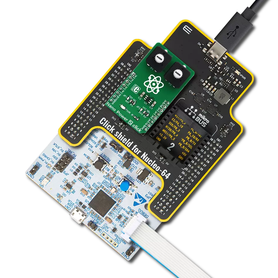
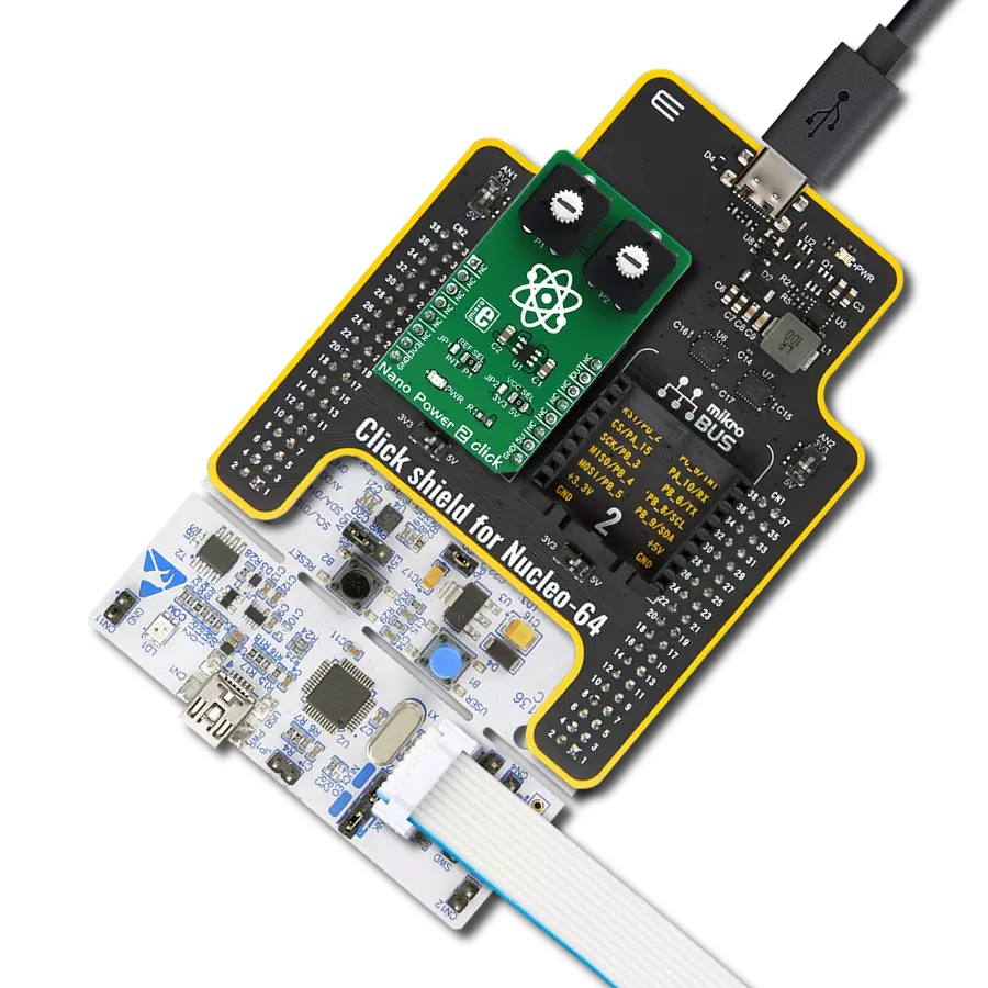
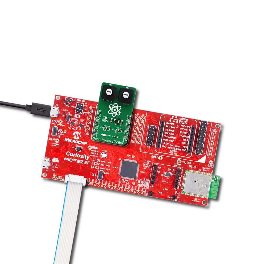
Nano Power 2 Click
Dev. board
Curiosity PIC32 MZ EF
Compiler
NECTO Studio
MCU
PIC32MZ2048EFM100
Detecting voltage differences becomes effortless with our nanoPower voltage comparator, offering efficient monitoring for various applications
A
A
Hardware Overview
How does it work?
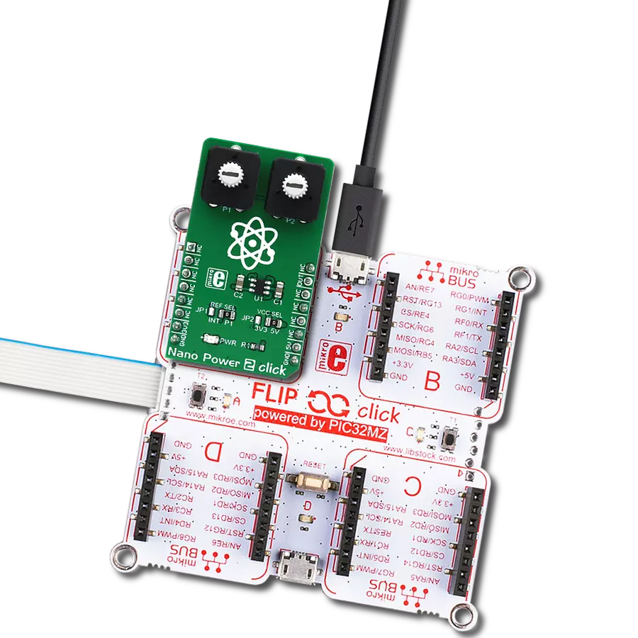
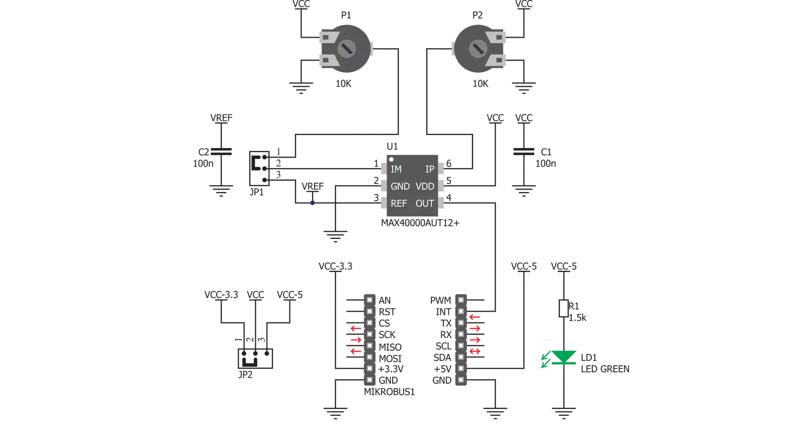
Nano Power 2 Click is based on the MAX40000, a nanoPower comparator with built-in reference from Analog Devices. This company offers several variants of the same IC, of which the used IC variant offers reference voltage of 1.2V on one of its pins. This reference voltage can be used at the comparator input, providing an accurate reference voltage throughout the fully operational temperature range, if required by the custom application. The IC itself requires a very low number of external components. It has two input pins, used as the comparator inputs. Each of these inputs can use -0.2V up to VCC + 0.2V. The VCC is the power supply voltage, and it can be selected via the SMD jumper labeled as LOGIC, between the 3.3V and 5V rails from the mikroBUS™. One of the comparator inputs, labeled as IM on the MAX40000 IC, is routable to either the onboard potentiometer (P1) or the REF pin of the IC, which provides the referent voltage of 1.2V. The routing can be done by another SMD jumper, labeled as REF SEL. The second comparator input (labeled as IP on the MAX40000 IC) is routed to the second
onboard potentiometer (P2). Both potentiometers can be used to set any voltage between the GND and VCC, which is selected by the LOGIC jumper, as described above. As mentioned before, the comparator has two inputs. One of them it is the inverting input and it is labeled as IM. The other input is a non-inverting input, labeled as IP. When the IP voltage becomes higher than the IM voltage, the output state becomes logic HIGH; otherwise, the output is set to a LOW state. A special case is when both voltages are very close, or at the same level, at any given moment. This would result in an appearance of oscillation at the output due to noise or parasitic feedback. To cope with this problem, an internal hysteresis of ±2.5mV is applied. The output of the MAX40000 IC is routed to the mikroBUS™ INT pin, labeled as OUT on the Click board™. The output stage employs a unique break-before-make topology, capable of rail-to-rail operation with up to ±2mA loads. The output stage also uses a unique design, which minimizes supply current surges when the switching occurs, resulting in very clean output
and low EM radiation. The MAX40000 has a push-pull output stage topology, which can both sink and source the current. Working with the Nano Power 2 click is very easy and straightforward. Only a single pin is used, which can be used to either trigger an interrupt (therefore it is routed to the INT pin), or its status can be read via the input pin of the host MCU. However, MikroElektronika provides a library that contains a function which can be used for simplified control of the Nano Power 2 click. The library also contains an example application, which demonstrates the use of the function. This example application can be used as a reference for custom designs. This Click board™ can operate with either 3.3V or 5V logic voltage levels selected via the VCC SEL jumper. This way, both 3.3V and 5V capable MCUs can use the communication lines properly. Also, this Click board™ comes equipped with a library containing easy-to-use functions and an example code that can be used as a reference for further development.

Features overview
Development board
Curiosity PIC32 MZ EF development board is a fully integrated 32-bit development platform featuring the high-performance PIC32MZ EF Series (PIC32MZ2048EFM) that has a 2MB Flash, 512KB RAM, integrated FPU, Crypto accelerator, and excellent connectivity options. It includes an integrated programmer and debugger, requiring no additional hardware. Users can expand
functionality through MIKROE mikroBUS™ Click™ adapter boards, add Ethernet connectivity with the Microchip PHY daughter board, add WiFi connectivity capability using the Microchip expansions boards, and add audio input and output capability with Microchip audio daughter boards. These boards are fully integrated into PIC32’s powerful software framework, MPLAB Harmony,
which provides a flexible and modular interface to application development a rich set of inter-operable software stacks (TCP-IP, USB), and easy-to-use features. The Curiosity PIC32 MZ EF development board offers expansion capabilities making it an excellent choice for a rapid prototyping board in Connectivity, IOT, and general-purpose applications.

Microcontroller Overview
MCU Card / MCU

Architecture
PIC32
MCU Memory (KB)
2048
Silicon Vendor
Microchip
Pin count
100
RAM (Bytes)
524288
Used MCU Pins
mikroBUS™ mapper
Take a closer look
Click board™ Schematic
Step by step
Project assembly

Start by selecting your development board and Click board™. Begin with the Curiosity PIC32 MZ EF as your development board.


Software Support
Library Description
This library contains API for Nano Power 2 Click driver.
Key functions:
nanopower2_check_output- Function gets output voltage from comparator
Open Source
Code example
The complete application code and a ready-to-use project are available through the NECTO Studio Package Manager for direct installation in the NECTO Studio. The application code can also be found on the MIKROE GitHub account.
/*!
 * \file
 * \brief Nano Power 2 Click example
 *
 * # Description
 * This application logs the comparators output value on USBUART.
 *
 * The demo application is composed of two sections :
 *
 * ## Application Init
 * Initializes GPIO driver.
 *
 * ## Application Task
 * Checks the comparator's output and logs output value on USBUART.
 *
 * \author Petar Suknjaja
 *
 */
// ------------------------------------------------------------------- INCLUDES

#include "board.h"
#include "log.h"
#include "nanopower2.h"

// ------------------------------------------------------------------ VARIABLES

static nanopower2_t nanopower2;
static log_t logger;

uint8_t out_check;
uint8_t out_check_prev;

// ------------------------------------------------------ APPLICATION FUNCTIONS

void application_init ( void )
{
    log_cfg_t log_cfg;
    nanopower2_cfg_t cfg;

    /**
     * Logger initialization.
     * Default baud rate: 115200
     * Default log level: LOG_LEVEL_DEBUG
     * @note If USB_UART_RX and USB_UART_TX
     * are defined as HAL_PIN_NC, you will
     * need to define them manually for log to work.
     * See @b LOG_MAP_USB_UART macro definition for detailed explanation.
     */
    LOG_MAP_USB_UART( log_cfg );
    log_init( &logger, &log_cfg );
    log_info( &logger, "---- Application Init ----" );

    //  Click initialization.
    nanopower2_cfg_setup( &cfg );
    NANOPOWER2_MAP_MIKROBUS( cfg, MIKROBUS_1 );
    nanopower2_init( &nanopower2, &cfg );

    log_printf( &logger, "NANO POWER 2 is initialized\r\n" );
    out_check_prev = 2;
}

void application_task ( void )
{
    out_check = nanopower2_check_output( &nanopower2 );
    if ( out_check != out_check_prev )
    {
        log_printf( &logger, "OUT is: %d\r\n", ( uint16_t ) out_check );

        out_check_prev = out_check;
    }
}

int main ( void )
{
    /* Do not remove this line or clock might not be set correctly. */
    #ifdef PREINIT_SUPPORTED
    preinit();
    #endif

    application_init( );

    for ( ; ; )
    {
        application_task( );
    }

    return 0;
}


// ------------------------------------------------------------------------ END
Additional Support
Resources
Category:Linear