Ensure your devices perform at their peak with NIS6150 and PIC32MZ2048EFM100
eFuse: Unlock reliability, enhance efficiency

Published Oct 09, 2023
Click board™
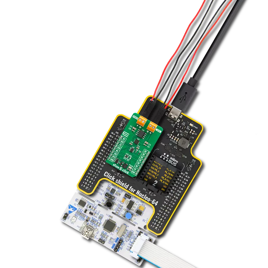
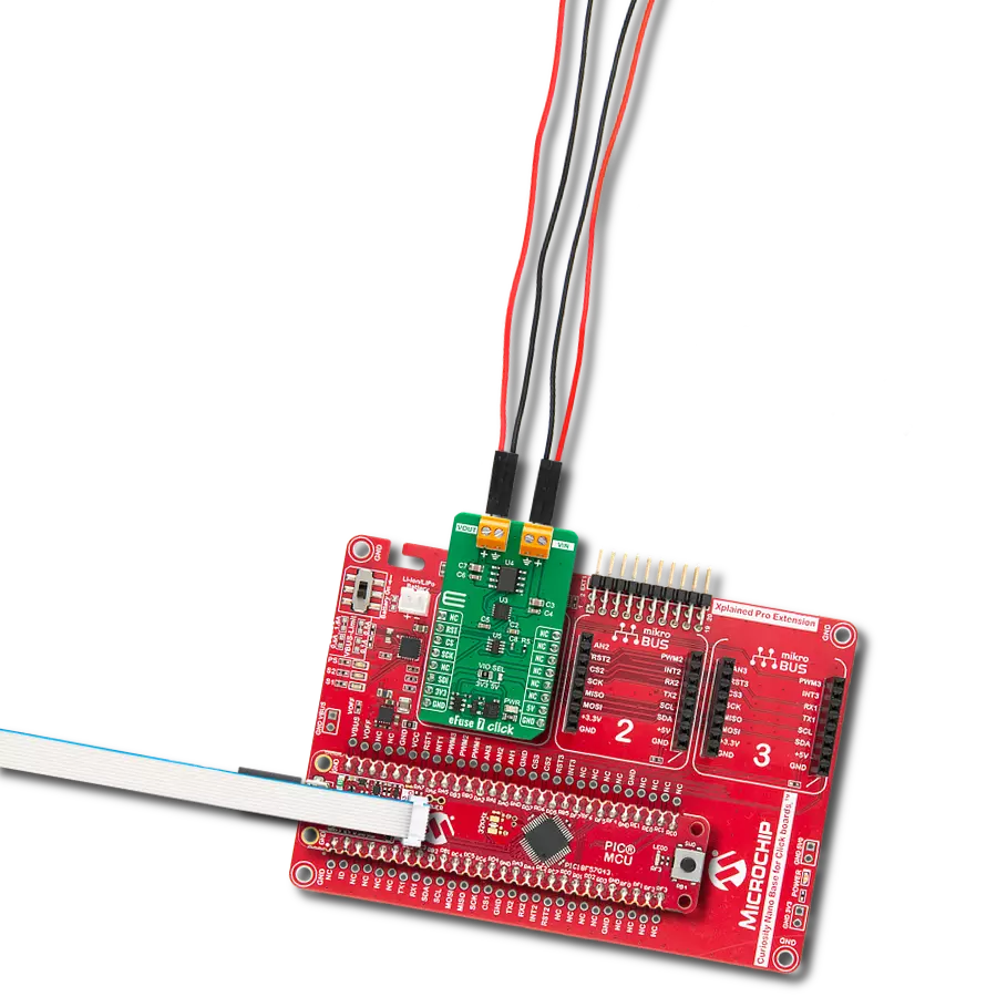
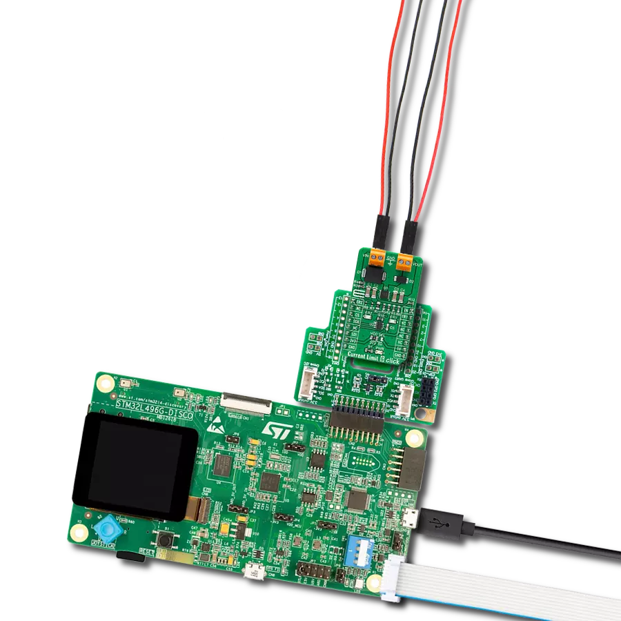
eFuse 3 Click
Dev. board
Curiosity PIC32 MZ EF
Compiler
NECTO Studio
MCU
PIC32MZ2048EFM100
Experience enhanced reliability and efficiency with our cutting-edge eFuse device, where voltage and current are managed effortlessly to safeguard your devices and elevate their performance
A
A
Hardware Overview
How does it work?
eFuse 3 Click is based on the NIS6150, a self-protected, resettable electronic fuse from ON Semiconductor that contains circuits to monitor the input voltage, output voltage, output current, and die temperature. It has an ENABLE feature with a separate ‘flag’ for fault identification, adjustable output current-limit protection with a thermal shutdown, and a current monitoring pin. The NIS6150 also includes an internal temperature sensing circuit that senses the temperature on the die of the power FET. If the temperature reaches 175°C, the device will shut down and remove power from the load. This Click board™ communicates with MCU through the 3-Wire SPI serial interface using the MCP3551, a 22-bit sigma-delta ADC from Microchip. The MCP3551 is used for current monitoring purposes by converting the output current from the NIS6150 IMON pin with a very high resolution of 22 bits and low noise to digital data, which can be obtained via the SPI interface of the Click board™. This ADC uses the
reference voltage, the 4.096V reference voltage level provided by the MCP1541 from Microchip powered from the +5V mikroBUS™ power rail, resulting in high accuracy and stability. A resistor that connects to the middle connector on this Click board™, labeled as Rlim, sets the overload and short circuit current limit levels. The VSL pin routed to the RST pin on the mikroBUS™ socket allows the overvoltage clamp to be set at a 5.7V or 6.5V minimum by pulling this pin to a low logic state. It monitors the output voltage, and if the input exceeds the output voltage, the gate drive of the main FET is reduced to limit the output. This is intended to allow operation through transients while protecting the load. If an overvoltage condition exists for many seconds, the device may overheat due to the voltage drop across the FET combined with the load current. In this event, the thermal protection circuit would shut down the device. The eFuse 3 Click also has two active additional pins of the mikroBUS™ socket, the INT
and PWM pins labeled as FLG and EN. The Enable feature, routed to the PWM pin on the mikroBUS™ socket, provides a digital interface to control the output of the eFuse. That’s why when this pin is pulled to a low logic state - the eFuse is turned OFF. On the other hand, the ‘flag’ pin routed to the INT pin on the mikroBUS™ socket sends information to the MCU regarding the state of the chip. If a thermal fault occurs, the voltage on this pin will go to a low state to signal a monitoring circuit that the device is in thermal shutdown. This Click board™ can operate with either 3.3V or 5V logic voltage levels selected via the VCC SEL jumper. This way, both 3.3V and 5V capable MCUs can use the communication lines properly. Also, this Click board™ comes equipped with a library containing easy-to-use functions and an example code that can be used as a reference for further development.

Features overview
Development board
Curiosity PIC32 MZ EF development board is a fully integrated 32-bit development platform featuring the high-performance PIC32MZ EF Series (PIC32MZ2048EFM) that has a 2MB Flash, 512KB RAM, integrated FPU, Crypto accelerator, and excellent connectivity options. It includes an integrated programmer and debugger, requiring no additional hardware. Users can expand
functionality through MIKROE mikroBUS™ Click™ adapter boards, add Ethernet connectivity with the Microchip PHY daughter board, add WiFi connectivity capability using the Microchip expansions boards, and add audio input and output capability with Microchip audio daughter boards. These boards are fully integrated into PIC32’s powerful software framework, MPLAB Harmony,
which provides a flexible and modular interface to application development a rich set of inter-operable software stacks (TCP-IP, USB), and easy-to-use features. The Curiosity PIC32 MZ EF development board offers expansion capabilities making it an excellent choice for a rapid prototyping board in Connectivity, IOT, and general-purpose applications.

Microcontroller Overview
MCU Card / MCU

Architecture
PIC32
MCU Memory (KB)
2048
Silicon Vendor
Microchip
Pin count
100
RAM (Bytes)
524288
Used MCU Pins
mikroBUS™ mapper
Take a closer look
Click board™ Schematic

Step by step
Project assembly

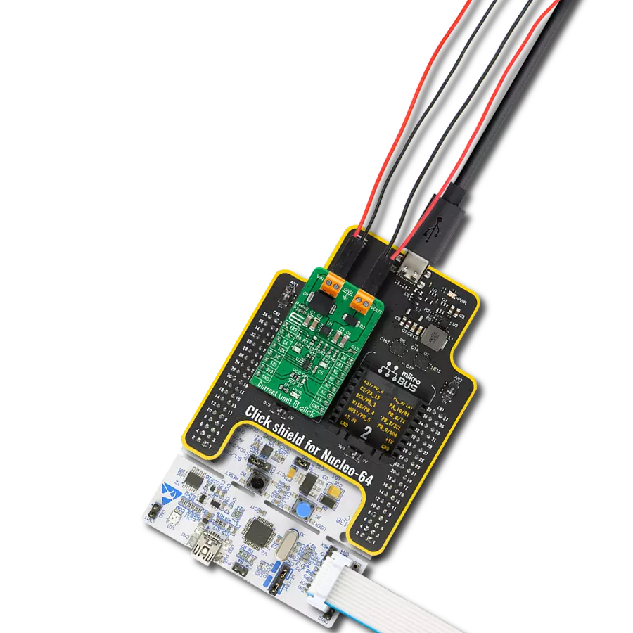
Start by selecting your development board and Click board™. Begin with the Curiosity PIC32 MZ EF as your development board.


Software Support
Library Description
This library contains API for eFuse 3 Click driver.
Key functions:
efuse3_get_current- eFuse 3 get current functionefuse3_get_flag- eFuse 3 get flag functionefuse3_reset- eFuse 3 reset function
Open Source
Code example
The complete application code and a ready-to-use project are available through the NECTO Studio Package Manager for direct installation in the NECTO Studio. The application code can also be found on the MIKROE GitHub account.
/*!
* @file main.c
* @brief eFuse3 Click example
*
* # Description
* This library contains API for the eFuse 3 Click driver.
* The library contains drivers to enable/disable the device,
* for reading ADC voltage, overflow status, output and current value [ A ].
*
* The demo application is composed of two sections :
*
* ## Application Init
* Initializes SPI driver and set default configuration.
*
* ## Application Task
* This is an example that demonstrates the use of the eFuse 3 Click board.
* Read and display device status information and current value [ A ].
* The eFuse 3 includes an overvoltage clamp the circuit that limits the output voltage
* during transients but does not shut the unit down,
* thereby allowing the load circuit to continue its operation.
* The Electronic Fuse is to limit current and current limit
* Current limit ( 0.1 A - 1.8 A ) depends on the choice of resistor wired
* on the Rlimit ( 1 Ohm - 15 Ohm ) connector.
* For example, for Rlimit resistance of 1 Ohm, current limit is 1 A
* ( 3.5 Ohm - 0.5 A, 7 Ohm - 0.25 A ).
* Read details from the ON Semiconductor NIS6150 datasheets.
* Results are being sent to the Usart Terminal where you can track their changes.
*
* @author Nenad Filipovic
*
*/
#include "board.h"
#include "log.h"
#include "efuse3.h"
static efuse3_t efuse3;
static log_t logger;
static float voltage;
static float current;
static uint8_t overflow_status;
void application_init ( void ) {
log_cfg_t log_cfg; /**< Logger config object. */
efuse3_cfg_t efuse3_cfg; /**< Click config object. */
/**
* Logger initialization.
* Default baud rate: 115200
* Default log level: LOG_LEVEL_DEBUG
* @note If USB_UART_RX and USB_UART_TX
* are defined as HAL_PIN_NC, you will
* need to define them manually for log to work.
* See @b LOG_MAP_USB_UART macro definition for detailed explanation.
*/
LOG_MAP_USB_UART( log_cfg );
log_init( &logger, &log_cfg );
log_info( &logger, " Application Init " );
// Click initialization.
efuse3_cfg_setup( &efuse3_cfg );
EFUSE3_MAP_MIKROBUS( efuse3_cfg, MIKROBUS_1 );
err_t init_flag = efuse3_init( &efuse3, &efuse3_cfg );
if ( init_flag == SPI_MASTER_ERROR ) {
log_error( &logger, " Application Init Error. " );
log_info( &logger, " Please, run program again... " );
for ( ; ; );
}
efuse3_default_cfg ( &efuse3 );
log_info( &logger, " Application Task " );
log_printf( &logger, "---------------------------\r\n" );
Delay_ms ( 100 );
}
void application_task ( void ) {
log_printf( &logger, " Status :" );
if ( efuse3_get_flag( &efuse3 ) == EFUSE3_FLAG_NORMAL_OPERATION ) {
log_printf( &logger, " Normal operation \r\n" );
} else {
log_printf( &logger, " Device OFF \r\n" );
if ( overflow_status == EFUSE3_OVERFLOW_HIGH ) {
log_printf( &logger, " Overflow high in the analog input voltage.\r\n" );
} else if ( overflow_status == EFUSE3_OVERFLOW_LOW ) {
log_printf( &logger, " Overflow low in the analog input voltage.\r\n" );
}
efuse3_reset( &efuse3 );
Delay_ms ( 1000 );
}
log_printf( &logger, "- - - - - - - - - - - - - - \r\n" );
efuse3_get_current( &efuse3, ¤t );
log_printf( &logger, " Current : %.5f A\r\n", current );
log_printf( &logger, "---------------------------\r\n" );
Delay_ms ( 1000 );
Delay_ms ( 1000 );
}
int main ( void )
{
/* Do not remove this line or clock might not be set correctly. */
#ifdef PREINIT_SUPPORTED
preinit();
#endif
application_init( );
for ( ; ; )
{
application_task( );
}
return 0;
}
// ------------------------------------------------------------------------ END
Additional Support
Resources
Category:Power Switch