Create immersive augmented reality experiences with ADPS9930 and PIC18F45K42
Navigating the world with proximity awareness

Published Oct 14, 2023
Click board™
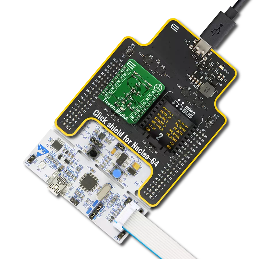
Proximity 7 Click
Dev. board
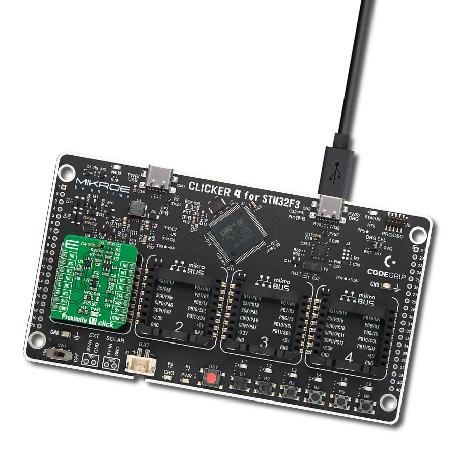
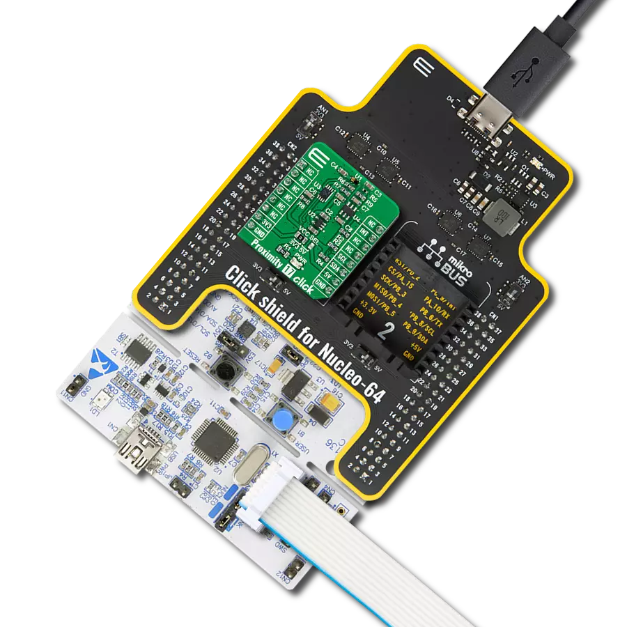
EasyPIC v8
Compiler
NECTO Studio
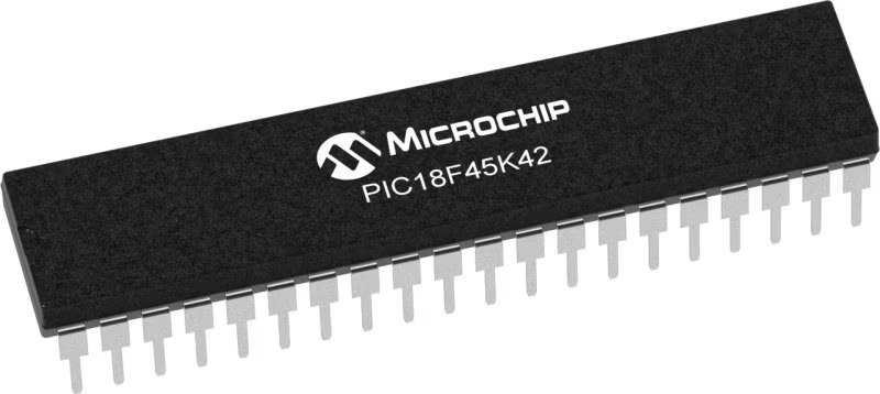
MCU
PIC18F45K42
Join us on a journey to discover how proximity detection is changing the way we perceive and interact with our surroundings
A
A
Hardware Overview
How does it work?
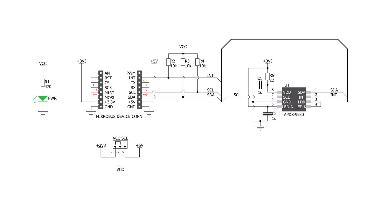
Proximity 7 Click is the ADPS9930, a digital ambient and proximity sensor from Broadcom. It is an accurate and reliable proximity and ambient light sensor, aimed towards the power saving in applications that use TFT or LCD panels. By offering a huge dynamic range, the ADPS9930 sensor allows to be placed behind a dark glass or a semi-transparent screen bezel, but also to be exposed to a bright sunlight. A proprietary design of the integrated constant-current LED driver enables plug and play proximity detection up to 100mm, eliminating the need for a calibration procedure. By integrating micro-optics elements within the casing, ADPS9930 greatly simplifies the application design. Proximity of an object is detected using an IR LED, which emits pulses of light towards the object. The amount of the reflected IR light is measured by an integrated IR photodiode on channel 1. During LED ON time, the amount of the reflected IR light is measured and integrated. The background IR light is also measured and integrated, during LED OFF time. It is then subtracted from the final result, allowing for an accurate measurement with the reduced amount of the background IR noise. After it has
been scaled to a 16-bit value, the final result is available on the output registers, in the LOW/HIGH byte format. Commonly, photosensitive elements are most sensitive to IR light. A human eye does cannot detect IR light. Therefore, the PD element has to filter out IR light so that only the visible part of the light is allowed through. The channel0 is equipped with such PD, making it usable for the ALS sensing. During the ALS measurement, both channels are measured. The datasheet of the ADPS9930 offers a conversion formula that can be used to obtain results in physical units (lx). These formulas also take the IR measurement from the channel 1 into the consideration, completely reducing its influence on the final result. By adjusting the integration time (also known as oversampling), the flickering effect of a fluorescent light can be completely eliminated. The extensive interrupt engine allows an optimized firmware to be written. Four registers are used to specify the low and the high threshold for the ALS and proximity measurements. Whenever these thresholds are exceeded, an interrupt status bit will be set in the respective register. The user has the ability to assign an external pin to an interrupt,
so the MCU can be alerted whenever an interrupt event occurs. The interrupt is generated whenever the threshold value is exceeded for a programmed number of times (interrupt persistence). This is useful to prevent false and erratic interrupt reporting. The power consumption is mainly affected by the integration time. It is a mean value of a programmable number of consecutive measurements, which is performed in order to reduce the noise, and improve the sensitivity, resolution, etc. However, it has an adverse impact on the overall power consumption, as the time frame during which the device is active, is extended: more measurements, longer activity. The internal state machine puts the ADPS9930 in a standby mode between readings, thus reducing the overall power consumption. Proximity 7 click uses an I2C interface to communicate with the host MCU. It is equipped with a SMD jumper labeled as VCC SEL. This jumper is used to select the power supply for the pull-up resistors on the I2C bus, allowing both 3.3V and 5V MCUs to be interfaced with this Click board™.


Features overview
Development board
EasyPIC v8 is a development board specially designed for the needs of rapid development of embedded applications. It supports many high pin count 8-bit PIC microcontrollers from Microchip, regardless of their number of pins, and a broad set of unique functions, such as the first-ever embedded debugger/programmer. The development board is well organized and designed so that the end-user has all the necessary elements, such as switches, buttons, indicators, connectors, and others, in one place. Thanks to innovative manufacturing technology, EasyPIC v8 provides a fluid and immersive working experience, allowing access anywhere and under any
circumstances at any time. Each part of the EasyPIC v8 development board contains the components necessary for the most efficient operation of the same board. In addition to the advanced integrated CODEGRIP programmer/debugger module, which offers many valuable programming/debugging options and seamless integration with the Mikroe software environment, the board also includes a clean and regulated power supply module for the development board. It can use a wide range of external power sources, including a battery, an external 12V power supply, and a power source via the USB Type-C (USB-C) connector.
Communication options such as USB-UART, USB DEVICE, and CAN are also included, including the well-established mikroBUS™ standard, two display options (graphical and character-based LCD), and several different DIP sockets. These sockets cover a wide range of 8-bit PIC MCUs, from the smallest PIC MCU devices with only eight up to forty pins. EasyPIC v8 is an integral part of the Mikroe ecosystem for rapid development. Natively supported by Mikroe software tools, it covers many aspects of prototyping and development thanks to a considerable number of different Click boards™ (over a thousand boards), the number of which is growing every day.

Microcontroller Overview
MCU Card / MCU
Architecture
PIC
MCU Memory (KB)
32
Silicon Vendor
Microchip
Pin count
40
RAM (Bytes)
2048
Used MCU Pins
mikroBUS™ mapper
Take a closer look
Click board™ Schematic
Step by step
Project assembly

Start by selecting your development board and Click board™. Begin with the EasyPIC v8 as your development board.


Track your results in real time
Application Output
1. Application Output - In Debug mode, the 'Application Output' window enables real-time data monitoring, offering direct insight into execution results. Ensure proper data display by configuring the environment correctly using the provided tutorial.

2. UART Terminal - Use the UART Terminal to monitor data transmission via a USB to UART converter, allowing direct communication between the Click board™ and your development system. Configure the baud rate and other serial settings according to your project's requirements to ensure proper functionality. For step-by-step setup instructions, refer to the provided tutorial.

3. Plot Output - The Plot feature offers a powerful way to visualize real-time sensor data, enabling trend analysis, debugging, and comparison of multiple data points. To set it up correctly, follow the provided tutorial, which includes a step-by-step example of using the Plot feature to display Click board™ readings. To use the Plot feature in your code, use the function: plot(*insert_graph_name*, variable_name);. This is a general format, and it is up to the user to replace 'insert_graph_name' with the actual graph name and 'variable_name' with the parameter to be displayed.

Software Support
Library Description
This library contains API for Proximity 7 Click driver.
Key functions:
proximity7_get_proximity_data- Get proximity dataproximity7_get_lux_level- Get lux levelproximity7_set_proximity_offset- Set proximity offset
Open Source
Code example
The complete application code and a ready-to-use project are available through the NECTO Studio Package Manager for direct installation in the NECTO Studio. The application code can also be found on the MIKROE GitHub account.
/*!
 * \file
 * \brief Proximity7 Click example
 *
 * # Description
 * This application give us lux level and proximiti data.
 *
 * The demo application is composed of two sections :
 *
 * ## Application Init
 * Initializes I2C driver and writes basic settings to device registers
 *
 * ## Application Task
 * Logs lux level and proximity data
 *
 * *note:*
 * - When setting LED drive strength please note that if "proximity drive level - PDL" bit in "configuration register" is set to 1, LED drive current values are reduced by 9.
 * - When setting wait time note that if "wait long - WLONG" bit is set to 1, time is 12x longer. Therefore if WLONG == 1 set time between 33ms and 8386.56ms.
 * - When setting ALS gain note that if "ALS gain level - AGL" bit is set to 1, ALS gains are scaled by 0.16, otherwise, they are scaled by 1.
 *
 * \author MikroE Team
 *
 */
// ------------------------------------------------------------------- INCLUDES

#include "board.h"
#include "log.h"
#include "proximity7.h"

// ------------------------------------------------------------------ VARIABLES


static proximity7_t proximity7;
static log_t logger;

void application_init ( void )
{
    log_cfg_t log_cfg;
    proximity7_cfg_t cfg;

    /**
     * Logger initialization.
     * Default baud rate: 115200
     * Default log level: LOG_LEVEL_DEBUG
     * @note If USB_UART_RX and USB_UART_TX
     * are defined as HAL_PIN_NC, you will
     * need to define them manually for log to work.
     * See @b LOG_MAP_USB_UART macro definition for detailed explanation.
     */
    LOG_MAP_USB_UART( log_cfg );
    log_init( &logger, &log_cfg );
    log_info( &logger, "---- Application Init ----" );

    //  Click initialization.

    proximity7_cfg_setup( &cfg );
    PROXIMITY7_MAP_MIKROBUS( cfg, MIKROBUS_1 );
    proximity7_init( &proximity7, &cfg );

    Delay_ms ( 100 );

    proximity7_default_cfg( &proximity7 );

    log_printf( &logger, "> > > Default configuration done < < <\r\n" );
}

void application_task ( void )
{
    uint8_t write_buffer[ 2 ];
    uint8_t read_buffer[ 1 ] ;
    float lux_level;
    uint16_t proximity;
    uint8_t als_valid;
    uint8_t proximity_valid;

    proximity7_generic_read( &proximity7, PROXIMITY7_STATUS | PROXIMITY7_REPEATED_BYTE, &read_buffer[ 0 ], 1 );

    als_valid = read_buffer[ 0 ] & PROXIMITY7_ALS_VALID_MASK;
    proximity_valid = read_buffer[ 0 ] & PROXIMITY7_PROXIMITY_VALID_MASK;

    if ( ( als_valid != 0 ) && ( proximity_valid != 0 ) )
    {
        log_printf( &logger, " " );

        lux_level = proximity7_get_lux_level( &proximity7 );
        log_printf( &logger, "> > > Lux level   : %f lx\r\n", lux_level );

        proximity = proximity7_get_proximity_data( &proximity7 );
        log_printf( &logger, "> > > Proximity   : %d\r\n", proximity );

        write_buffer[ 0 ] = PROXIMITY7_SPECIAL_FUNCTION | PROXIMITY7_PROXIMITY_AND_ALS_INT_PIN_CLEAR;
        proximity7_generic_write( &proximity7, PROXIMITY7_SPECIAL_FUNCTION | PROXIMITY7_PROXIMITY_AND_ALS_INT_PIN_CLEAR, &write_buffer[ 0 ], 1 );
    }

    Delay_ms ( 300 );
}

int main ( void )
{
    /* Do not remove this line or clock might not be set correctly. */
    #ifdef PREINIT_SUPPORTED
    preinit();
    #endif

    application_init( );

    for ( ; ; )
    {
        application_task( );
    }

    return 0;
}


// ------------------------------------------------------------------------ END