Ensure precise object detection with MAX44000 and PIC18F57Q43
See what's near with clarity!

Published Feb 13, 2024
Click board™
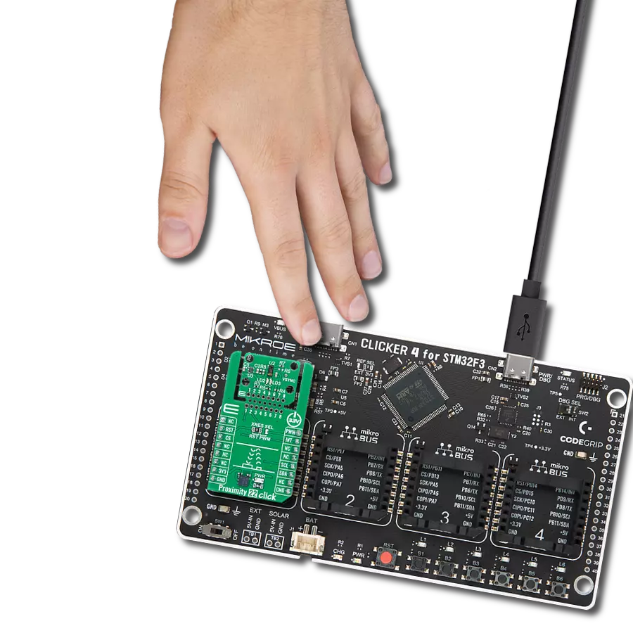
PROXIMITY 2 Click
Dev. board
Curiosity Nano with PIC18F57Q43
Compiler
NECTO Studio
MCU
PIC18F57Q43
Enhance safety and efficiency with real-time detection of nearby objects or individuals
A
A
Hardware Overview
How does it work?
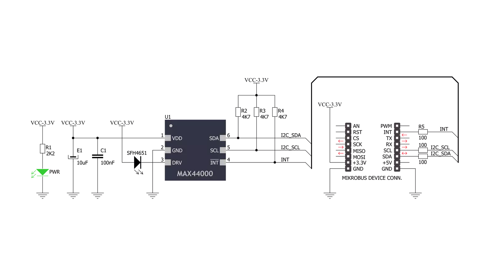
Proximity 2 Click is based on the MAX44000, a wide-dynamic range ambient light sensor with an integrated infrared proximity sensor from Analog Devices. Designed using proprietary BiCMOS technology, the MAX44000 combines three optical sensors, two A/D converters, and digital functionality into one package. A MAX44000's photodiode array converts the light to a current, processed by low-power circuitry into a digital value which is then stored in an output register and later read by an I2C serial interface. This feature allows the MAX44000 to replicate the human eye's optical response in various environments. The infrared proximity photodiodes are optimized for better sensitivity for
near-infrared signals, specifically 850nm, and can be used for proximity sensor measurements. The proximity sensing uses an external, pulsed infrared LED source, the SFH 4651-Z, to emit controlled amounts of infrared radiation. When the SFH 4651-Z reflects some of this infrared radiation to the MAX44000, it is detected by the integrated light detector and then used to determine the object's proximity to the sensor. It is essential to note that different objects at the same distance from the sensor can reflect different amounts of infrared radiation depending on their texture and color. The MAX44000 communicates with the MCU using the standard I2C 2-Wire interface with a maximum frequency of 400kHz. This Click board™
also supports a programmable interrupt feature, routed to the INT pin on the mikroBUS™ socket, that simplifies and improves system efficiency by eliminating the need to poll a sensor for a data (ambient light or proximity receive interrupt has occurred), resulting in a significant power saving. This Click board™ can be operated only with a 3.3V logic voltage level. The board must perform appropriate logic voltage level conversion before using MCUs with different logic levels. However, the Click board™ comes equipped with a library containing functions and an example code that can be used as a reference for further development.

Features overview
Development board
PIC18F57Q43 Curiosity Nano evaluation kit is a cutting-edge hardware platform designed to evaluate microcontrollers within the PIC18-Q43 family. Central to its design is the inclusion of the powerful PIC18F57Q43 microcontroller (MCU), offering advanced functionalities and robust performance. Key features of this evaluation kit include a yellow user LED and a responsive
mechanical user switch, providing seamless interaction and testing. The provision for a 32.768kHz crystal footprint ensures precision timing capabilities. With an onboard debugger boasting a green power and status LED, programming and debugging become intuitive and efficient. Further enhancing its utility is the Virtual serial port (CDC) and a debug GPIO channel (DGI
GPIO), offering extensive connectivity options. Powered via USB, this kit boasts an adjustable target voltage feature facilitated by the MIC5353 LDO regulator, ensuring stable operation with an output voltage ranging from 1.8V to 5.1V, with a maximum output current of 500mA, subject to ambient temperature and voltage constraints.

Microcontroller Overview
MCU Card / MCU

Architecture
PIC
MCU Memory (KB)
128
Silicon Vendor
Microchip
Pin count
48
RAM (Bytes)
8196
You complete me!
Accessories
Curiosity Nano Base for Click boards is a versatile hardware extension platform created to streamline the integration between Curiosity Nano kits and extension boards, tailored explicitly for the mikroBUS™-standardized Click boards and Xplained Pro extension boards. This innovative base board (shield) offers seamless connectivity and expansion possibilities, simplifying experimentation and development. Key features include USB power compatibility from the Curiosity Nano kit, alongside an alternative external power input option for enhanced flexibility. The onboard Li-Ion/LiPo charger and management circuit ensure smooth operation for battery-powered applications, simplifying usage and management. Moreover, the base incorporates a fixed 3.3V PSU dedicated to target and mikroBUS™ power rails, alongside a fixed 5.0V boost converter catering to 5V power rails of mikroBUS™ sockets, providing stable power delivery for various connected devices.

Used MCU Pins
mikroBUS™ mapper
Take a closer look
Click board™ Schematic
Step by step
Project assembly

Start by selecting your development board and Click board™. Begin with the Curiosity Nano with PIC18F57Q43 as your development board.


Track your results in real time
Application Output
1. Application Output - In Debug mode, the 'Application Output' window enables real-time data monitoring, offering direct insight into execution results. Ensure proper data display by configuring the environment correctly using the provided tutorial.

2. UART Terminal - Use the UART Terminal to monitor data transmission via a USB to UART converter, allowing direct communication between the Click board™ and your development system. Configure the baud rate and other serial settings according to your project's requirements to ensure proper functionality. For step-by-step setup instructions, refer to the provided tutorial.

3. Plot Output - The Plot feature offers a powerful way to visualize real-time sensor data, enabling trend analysis, debugging, and comparison of multiple data points. To set it up correctly, follow the provided tutorial, which includes a step-by-step example of using the Plot feature to display Click board™ readings. To use the Plot feature in your code, use the function: plot(*insert_graph_name*, variable_name);. This is a general format, and it is up to the user to replace 'insert_graph_name' with the actual graph name and 'variable_name' with the parameter to be displayed.

Software Support
Library Description
This library contains API for Proximity 2 Click driver.
Key functions:
proximity2_read_prox- Read PROX Data Register functionproximity2_read_als- Read ALS Data Registers function
Open Source
Code example
The complete application code and a ready-to-use project are available through the NECTO Studio Package Manager for direct installation in the NECTO Studio. The application code can also be found on the MIKROE GitHub account.
/*!
 * \file
 * \brief Proximity2 Click example
 *
 * # Description
 * This is an example that shows the most important
 * functions that Proximity 2 Click has.
 *
 * The demo application is composed of two sections :
 *
 * ## Application Init
 * Configuring Clicks and log objects.
 * Setting the Click in the default configuration.
 *
 * ## Application Task
 * Shows the most important proximity and ambient value.
 *
 * \author MikroE Team
 *
 */
// ------------------------------------------------------------------- INCLUDES

#include "board.h"
#include "log.h"
#include "proximity2.h"

// ------------------------------------------------------------------ VARIABLES

static proximity2_t proximity2;
static log_t logger;

static uint8_t proxi_val;
static uint16_t ambient;

// ------------------------------------------------------ APPLICATION FUNCTIONS

void application_init ( void )
{
    log_cfg_t log_cfg;
    proximity2_cfg_t cfg;

    /**
     * Logger initialization.
     * Default baud rate: 115200
     * Default log level: LOG_LEVEL_DEBUG
     * @note If USB_UART_RX and USB_UART_TX
     * are defined as HAL_PIN_NC, you will
     * need to define them manually for log to work.
     * See @b LOG_MAP_USB_UART macro definition for detailed explanation.
     */
    LOG_MAP_USB_UART( log_cfg );
    log_init( &logger, &log_cfg );
    log_info( &logger, "Application Init" );

    //  Click initialization.

    proximity2_cfg_setup( &cfg );
    PROXIMITY2_MAP_MIKROBUS( cfg, MIKROBUS_1 );
    proximity2_init( &proximity2, &cfg );

    proximity2_default_cfg ( &proximity2 );

    log_info( &logger, "Application Init" );
    Delay_ms ( 1000 );
}

void application_task ( void )
{
    proxi_val =  proximity2_read_prox ( &proximity2 );
    ambient = proximity2_read_als ( &proximity2 );

    log_printf( &logger, " Proximity ADC : %d \r\n", (uint16_t)proxi_val );

    log_printf( &logger, " Light    : %d \r\n", ambient );

    log_printf( &logger, "------------------\r\n" );

    Delay_ms ( 300 );
}

int main ( void )
{
    /* Do not remove this line or clock might not be set correctly. */
    #ifdef PREINIT_SUPPORTED
    preinit();
    #endif

    application_init( );

    for ( ; ; )
    {
        application_task( );
    }

    return 0;
}


// ------------------------------------------------------------------------ END
Additional Support
Resources
Category:Proximity