Achieve broadcast brilliance with AK1595 and PIC18LF47K40
Low-energy Bluetooth transmitter
Published Jul 29, 2023
Click board™
BLE TX Click
Dev. board
EasyPIC v8
Compiler
NECTO Studio
MCU
PIC18LF47K40
Our cutting-edge BLE transmitter empowers you to broadcast signals with unparalleled efficiency, allowing seamless communication and data exchange between devices for a wide range of wireless applications
A
A
Hardware Overview
How does it work?
BLE TX Click is based on the AK1595, a low-power Bluetooth 5.2 transmitter from AKM Semiconductor. The AK1595 incorporates proprietary algorithm software and can achieve Bluetooth Low Energy transmitter (BLE TX) functionality without a particular development environment and programming required for conventional Bluetooth SoCs. The BLE function can be realized by simply setting the data to be transmitted to the built-in register, making it ideal for applications that add the BLE function to existing microcomputers. The AK1595 has high-speed responsiveness that starts advertising transmission within 3ms from the Power-Down state. This fact allows the power consumption between transmissions to be kept on Standby at a low power consumption of 15nA typical by controlling BLE advertising transmission, which is intermittent transmission, to be in the whole Power-Down state. Also, it supports 1Mbps GFSK +/- modulation, where the modulation clock is
generated from a 32MHz onboard clock generator. BLE TX Click provides the possibility of using both UART and I2C interfaces. The AK1595 configures its selected interface via three GPIO pins labeled as U/I, S1, and S0 routed on the CS, AN, and PWM pins of the mikroBUS™ socket. In addition to the I/O pin on the mikroBUS™ socket, which activates a particular serial communication based on the set logical level, this Click board™ also has two jumpers intended for the hardware interface selection itself. The choice can be made by positioning SMD jumpers labeled as COMM SEL in an appropriate position. Note that all the jumpers' positions must be on the same side, or the Click board™ may become unresponsive. When the UART interface is selected, the UART controller block is initialized when the S1 pin detects low logic state for more than 1μs. Also, by setting a specific logic level on pin S0, the user can set the baud rate of the UART communication itself (set S0 to a low logic state for 9600bps or S0
to a high logic state for 115200bps). The I2C interface of AK1595 supports the Standard with a clock frequency of up to 100kHz and the Fast Mode with up to 400kHz. Also, this Click board™ has a Reset pin routed to the RST pin on the mikroBUS™ socket, which holds registers in their default states until the RST pin is set to a logic low state. BLE TX Click possesses a miniature coaxial N.FL series antenna connector which, in combination with IPEX-SMA cable, allows connecting the appropriate antenna, such as WIFI Rubber Antenna 2.4GHz right angle SMA or WIFI Rubber Antenna for improved range and received signal strength. This Click board™ can be operated only with a 3.3V logic voltage level. The board must perform appropriate logic voltage level conversion before using MCUs with different logic levels. Also, it comes equipped with a library containing functions and an example code that can be used, as a reference, for further development.


Features overview
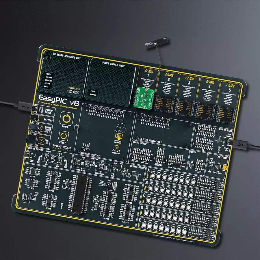
Development board
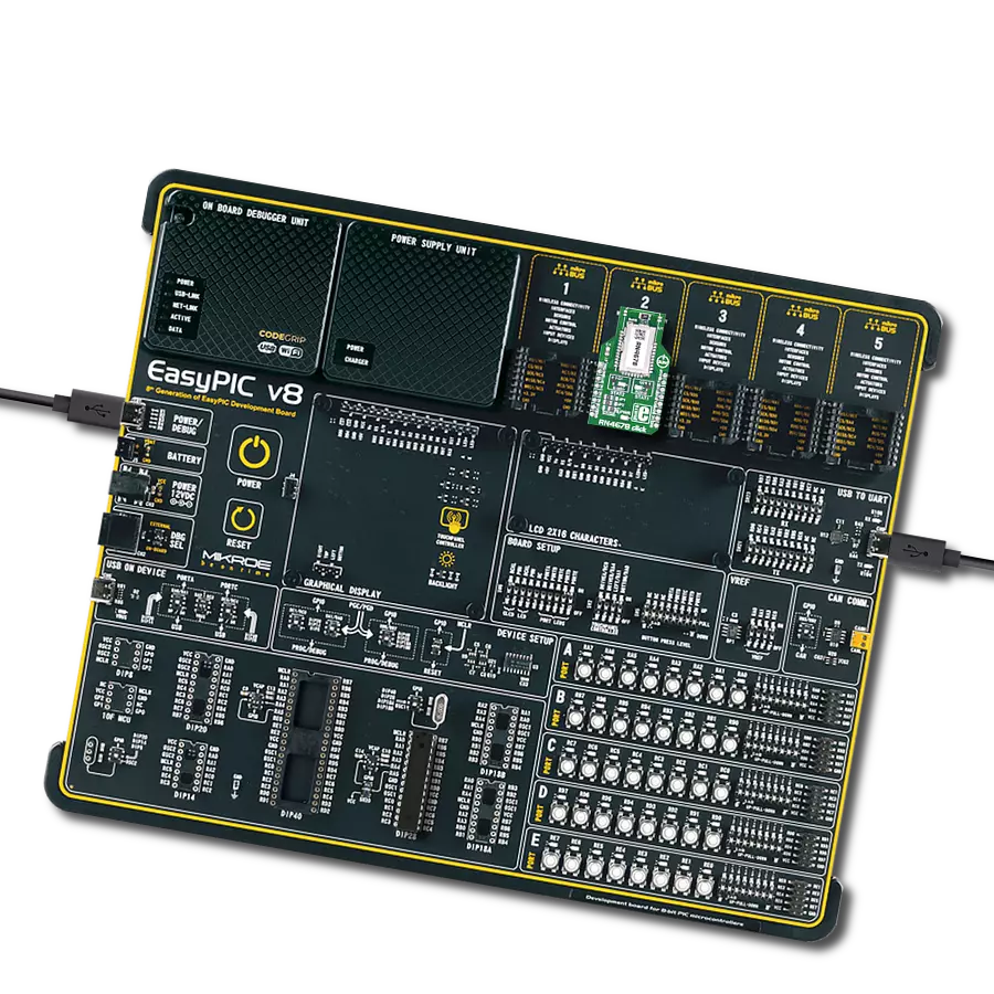
EasyPIC v8 is a development board specially designed for the needs of rapid development of embedded applications. It supports many high pin count 8-bit PIC microcontrollers from Microchip, regardless of their number of pins, and a broad set of unique functions, such as the first-ever embedded debugger/programmer. The development board is well organized and designed so that the end-user has all the necessary elements, such as switches, buttons, indicators, connectors, and others, in one place. Thanks to innovative manufacturing technology, EasyPIC v8 provides a fluid and immersive working experience, allowing access anywhere and under any
circumstances at any time. Each part of the EasyPIC v8 development board contains the components necessary for the most efficient operation of the same board. In addition to the advanced integrated CODEGRIP programmer/debugger module, which offers many valuable programming/debugging options and seamless integration with the Mikroe software environment, the board also includes a clean and regulated power supply module for the development board. It can use a wide range of external power sources, including a battery, an external 12V power supply, and a power source via the USB Type-C (USB-C) connector.
Communication options such as USB-UART, USB DEVICE, and CAN are also included, including the well-established mikroBUS™ standard, two display options (graphical and character-based LCD), and several different DIP sockets. These sockets cover a wide range of 8-bit PIC MCUs, from the smallest PIC MCU devices with only eight up to forty pins. EasyPIC v8 is an integral part of the Mikroe ecosystem for rapid development. Natively supported by Mikroe software tools, it covers many aspects of prototyping and development thanks to a considerable number of different Click boards™ (over a thousand boards), the number of which is growing every day.

Microcontroller Overview
MCU Card / MCU
Architecture
PIC
MCU Memory (KB)
128
Silicon Vendor
Microchip
Pin count
40
RAM (Bytes)
3728
You complete me!
Accessories
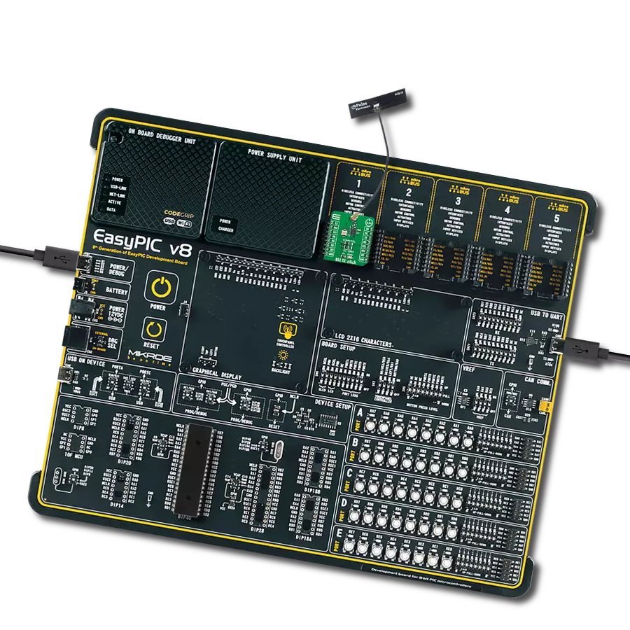
WiFi 2.4GHz/5.4GHz Active FPC Antenna (W3918B0100) is an active flat patch antenna from Pulse Electronics ideal for WiFi 6E, Bluetooth, ZigBee, ISM band radios, IoT, M2M, and more. With dual-frequency capabilities in a range of 2.4-2.5GHz and 4.9-5.925GHz, with central frequencies of 2.4GHz and 5.4GHz, this flat patch antenna boasts a gain of typical 3dBi and omnidirectional radiation pattern. Measuring 35.2x8.5x0.15mm, the antenna size is compact yet efficient, and with a nominal impedance of 50Ω, it's designed to work seamlessly with your existing setup. The FPC material used for the antenna ensures durability and reliability, and with a power rating of 2W, you can trust it to perform consistently. The U.FL connector type and 10mm cable length make for easy integration into your system, and with its superior performance, the WiFi 2.4GHz/5.4GHz Active FPC Antenna is the perfect choice for your wireless communication and networking needs.

Used MCU Pins
mikroBUS™ mapper
Take a closer look
Click board™ Schematic

Step by step
Project assembly

Start by selecting your development board and Click board™. Begin with the EasyPIC v8 as your development board.


Track your results in real time
Application Output
1. Application Output - In Debug mode, the 'Application Output' window enables real-time data monitoring, offering direct insight into execution results. Ensure proper data display by configuring the environment correctly using the provided tutorial.

2. UART Terminal - Use the UART Terminal to monitor data transmission via a USB to UART converter, allowing direct communication between the Click board™ and your development system. Configure the baud rate and other serial settings according to your project's requirements to ensure proper functionality. For step-by-step setup instructions, refer to the provided tutorial.

3. Plot Output - The Plot feature offers a powerful way to visualize real-time sensor data, enabling trend analysis, debugging, and comparison of multiple data points. To set it up correctly, follow the provided tutorial, which includes a step-by-step example of using the Plot feature to display Click board™ readings. To use the Plot feature in your code, use the function: plot(*insert_graph_name*, variable_name);. This is a general format, and it is up to the user to replace 'insert_graph_name' with the actual graph name and 'variable_name' with the parameter to be displayed.

Software Support
Library Description
This library contains API for BLE TX Click driver.
Key functions:
bletx_start_advertising- BLE TX start advertising functionbletx_set_configuration- BLE TX configuration setting functionbletx_create_eddystone_uri- BLE TX create Eddystoneâ„¢ URI data packet function
Open Source
Code example
The complete application code and a ready-to-use project are available through the NECTO Studio Package Manager for direct installation in the NECTO Studio. The application code can also be found on the MIKROE GitHub account.
/*!
 * @file main.c
 * @brief BleTx Click example
 *
 * # Description
 * This library contains API for the BLE TX Click driver.
 * This example processes data from BLE TX Click, BLE TX Click
 * Bluetooth® Low Energy compliant advertising transmission
 * can be achieved by simply configuring the transmission power,
 * data, and transmission - start trigger.
 *
 * The demo application is composed of two sections :
 *
 * ## Application Init
 * Initialization of I2C module and log UART.
 * Initializes driver and set performs the default configuration.
 * Configure Bluetooth Low Energy Beacons to transmit so-called advertising frames.
 * Configuration of the Eddystone URI, UID, or TLM
 * Bluetooth Low Energy Beacons profile task depends on uncommented code.
 * Eddystone ( URI ) : broadcasts a URL of at most 15 characters
 * that redirects to a website that is secured using SSL.
 * Eddystone ( UID ) : broadcasts an identifying code
 * that allows apps to retrieve information from app servers.
 * Eddystone ( TLM ) : broadcasts information about the beacon,
 * include battery level, sensor data, or other relevant information
 * to beacon administrators.
 *
 * ## Application Task
 * This is an example that shows the use of a BLE TX Click board™.
 * In this example, the application turns the selected advertising frames
 * ON and OFF for a period of 10 seconds.
 *
 * @note
 * For scanning BLE TX Click board™ BLE Scanner is a recommended Android application
 * and you can find it at the link:
 * https://play.google.com/store/apps/details?id=com.macdom.ble.blescanner
 *
 * @author Nenad Filipovic
 *
 */

#include "board.h"
#include "log.h"
#include "bletx.h"

static bletx_t bletx;
static log_t logger;

#define URI
// #define UID
// #define TLM

bletx_adv_cfg_t adv_cfg;
bletx_eddystone_data_t adv_data;

void application_init ( void )
{
    log_cfg_t log_cfg;      /**< Logger config object. */
    bletx_cfg_t bletx_cfg;  /**< Click config object. */

    /**
     * Logger initialization.
     * Default baud rate: 115200
     * Default log level: LOG_LEVEL_DEBUG
     * @note If USB_UART_RX and USB_UART_TX
     * are defined as HAL_PIN_NC, you will
     * need to define them manually for log to work.
     * See @b LOG_MAP_USB_UART macro definition for detailed explanation.
     */
    LOG_MAP_USB_UART( log_cfg );
    log_init( &logger, &log_cfg );
    log_info( &logger, " Application Init " );

    // Click initialization.
    bletx_cfg_setup( &bletx_cfg );
    BLETX_MAP_MIKROBUS( bletx_cfg, MIKROBUS_1 );
    if ( I2C_MASTER_ERROR == bletx_init( &bletx, &bletx_cfg ) )
    {
        log_error( &logger, " Communication init." );
        for ( ; ; );
    }

    bletx_default_cfg ( &bletx );
    Delay_ms ( 1000 );

    adv_cfg.adv_ch_1_frequency = ADVCH1_37_Ch_2402_MHz;
    adv_cfg.adv_ch_2_frequency = ADVCH2_38_Ch_2426_MHz;
    adv_cfg.adv_ch_3_frequency = ADVCH3_39_Ch_2480_MHz;
    adv_cfg.tx_output_power = TX_POWER_0_dBm;
    adv_cfg.txdata_loop = 0;
    adv_cfg.txdata_cw = 0;
    adv_cfg.eventnum = 0;
    adv_cfg.advdelay_enb = BLETX_ADV_DELAY_ENABLE;
    adv_cfg.avdintvl_interval_ms = 0;
    adv_cfg.crc_enb = BLETX_CRC_ENABLE;
    adv_cfg.white_enb = BLETX_WHITE_ENABLE;
    adv_cfg.pdu_len = 39;

    adv_cfg.uuid[ 0 ] = 0x11;
    adv_cfg.uuid[ 1 ] = 0x22;
    adv_cfg.uuid[ 2 ] = 0x33;
    adv_cfg.uuid[ 3 ] = 0x44;
    adv_cfg.uuid[ 4 ] = 0x55;
    adv_cfg.uuid[ 5 ] = 0x66;

    if ( BLETX_OK != bletx_set_configuration( &bletx, adv_cfg ) )
    {
        log_error( &logger, " Set configuration." );
        for ( ; ; );
    }
    Delay_ms ( 100 );

#ifdef URI
    adv_data.length_of_service_list = 3;
    adv_data.param_service_list = 3;
    adv_data.eddystone_id = BLETX_EDDYSTONE_SERVICE_UUID;
    adv_data.length_of_service_data = 13;
    adv_data.service_data = BLETX_EDDYSTONE_SERVICE_DATA_TYPE_VALUE;
    adv_data.frame_type_url = BLETX_EDDYSTONE_FRAME_TYPE_URL;
    adv_data.power = BLETX_TX_POWER_LVL_MODE_LOWEST;
    adv_data.spec_data = BLETX_EDDYSTONE_SPEC_DATA_HTTPS_WWW;
    adv_data.advdata_url[ 0 ] = 'm';
    adv_data.advdata_url[ 1 ] = 'i';
    adv_data.advdata_url[ 2 ] = 'k';
    adv_data.advdata_url[ 3 ] = 'r';
    adv_data.advdata_url[ 4 ] = 'o';
    adv_data.advdata_url[ 5 ] = 'e';
    adv_data.domain = BLETX_CHARACTER_CODES_DOT_COM;

    bletx_create_eddystone_uri ( &bletx, adv_data );
#endif

#ifdef UID
    adv_data.length_of_service_list = 3;
    adv_data.param_service_list = 3;
    adv_data.eddystone_id = BLETX_EDDYSTONE_SERVICE_UUID;
    adv_data.length_of_service_data = 23;
    adv_data.service_data = BLETX_EDDYSTONE_SERVICE_DATA_TYPE_VALUE;
    adv_data.frame_type_url = BLETX_EDDYSTONE_FRAME_TYPE_UID;
    adv_data.power = BLETX_TX_POWER_LVL_MODE_LOW;

    adv_data.name_space_id[ 0 ] = 0x01;
    adv_data.name_space_id[ 1 ] = 0x02;
    adv_data.name_space_id[ 2 ] = 0x03;
    adv_data.name_space_id[ 3 ] = 0x04;
    adv_data.name_space_id[ 4 ] = 0x05;
    adv_data.name_space_id[ 5 ] = 0x06;
    adv_data.name_space_id[ 6 ] = 0x07;
    adv_data.name_space_id[ 7 ] = 0x08;
    adv_data.name_space_id[ 8 ] = 0x09;
    adv_data.name_space_id[ 9 ] = 0x0A;

    adv_data.instance_id[ 0 ] = 0x01;
    adv_data.instance_id[ 1 ] = 0x23;
    adv_data.instance_id[ 2 ] = 0x45;
    adv_data.instance_id[ 3 ] = 0x67;
    adv_data.instance_id[ 4 ] = 0x89;
    adv_data.instance_id[ 5 ] = 0xAB;

    bletx_create_eddystone_uid ( &bletx, adv_data );
#endif

#ifdef TLM
    adv_data.length_of_service_list = 3;
    adv_data.param_service_list = 3;
    adv_data.eddystone_id = BLETX_EDDYSTONE_SERVICE_UUID;
    adv_data.length_of_service_data = 23;
    adv_data.service_data = BLETX_EDDYSTONE_SERVICE_DATA_TYPE_VALUE;
    adv_data.frame_type_url = BLETX_EDDYSTONE_FRAME_TYPE_TLM;
    adv_data.tlm_version = 0;          // TLM version
    adv_data.spec_data = BLETX_EDDYSTONE_SPEC_DATA_TLM;

    adv_data.battery_voltage = 3600;
    adv_data.beacon_temperature = 20.21;
    adv_data.pdu_count = 11223344;

    bletx_create_eddystone_tlm ( &bletx, adv_data );
#endif

    log_info( &logger, " Application Task " );
    Delay_ms ( 100 );
}

void application_task ( void )
{
    log_printf( &logger, ">>>\tStart Advertising \r\n" );
    bletx_start_advertising( &bletx );
    // 10 seconds delay
    Delay_ms ( 1000 );
    Delay_ms ( 1000 );
    Delay_ms ( 1000 );
    Delay_ms ( 1000 );
    Delay_ms ( 1000 );
    Delay_ms ( 1000 );
    Delay_ms ( 1000 );
    Delay_ms ( 1000 );
    Delay_ms ( 1000 );
    Delay_ms ( 1000 );

    log_printf( &logger, ">>>\tStop Advertising \r\n" );
    bletx_stop_advertising( &bletx );
    // 10 seconds delay
    Delay_ms ( 1000 );
    Delay_ms ( 1000 );
    Delay_ms ( 1000 );
    Delay_ms ( 1000 );
    Delay_ms ( 1000 );
    Delay_ms ( 1000 );
    Delay_ms ( 1000 );
    Delay_ms ( 1000 );
    Delay_ms ( 1000 );
    Delay_ms ( 1000 );
}

int main ( void )
{
    /* Do not remove this line or clock might not be set correctly. */
    #ifdef PREINIT_SUPPORTED
    preinit();
    #endif

    application_init( );

    for ( ; ; )
    {
        application_task( );
    }

    return 0;
}

// ------------------------------------------------------------------------ END