Identify and optimize energy use in appliances with PAC1944 and PIC18LF45K22
Watts up with DC power? Discover the future of energy monitoring

Published Sep 30, 2023
Click board™
PAC1944 Click
Dev. board
EasyPIC v8
Compiler
NECTO Studio
MCU
PIC18LF45K22
Experience the future of power management with our DC energy monitor, designed to simplify energy tracking and optimize your lifestyle
A
A
Hardware Overview
How does it work?
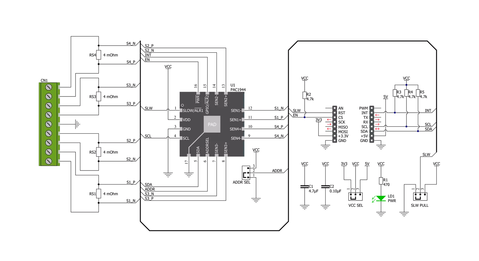
PAC1944 Click is based on the PAC1944, a four-channel, bidirectional, high-side current-sensing solution with precision voltage measurement capabilities, DSP for power calculation, and a power accumulator from Microchip Technology. Its real-time calibration minimizes offset and gain errors. Four current sense shunt resistors are connected to PAC1944’s integrated current sense amplifier. Electricity is brought to shunts via screw terminals where the middle screw connector represents GND used for bus voltage monitoring. Bus voltage, sense resistor voltage, and accumulated proportional power are stored in registers for retrieval by the MCU. One major feature of the PAC1944 design is a set of digital comparators that allows the user to detect over/under voltage, over/undercurrent, and overpower against user-programmed limits for each channel and generate an alert when the threshold is exceeded. The digital circuitry of the PAC1944 performs power calculations and energy accumulation, which enables energy monitoring with integration periods of up to one year or longer. After the Start-Up sequence, the
PAC1944 is Active and begins sampling the inputs sequentially. Voltage and current are sampled for all active channels at 1024 samples/second by default, and power is calculated and accumulated. PAC1944 Click communicates with MCU using the standard I2C 2-Wire interface to read data and configure settings, supporting Fast Mode operation with a clock frequency up to 1MHz and High-Speed Mode up to 3.4MHz. Besides, it also allows the choice of the least significant bit of its I2C slave address by positioning the SMD jumper labeled ADDR SEL to an appropriate position marked as 0 and 1. The Power-Down pin, labeled as EN and routed to the CS pin of the mikroBUS™ socket, optimizes power consumption and is used for power on/off purposes. All circuits, including the interface pins, are inactive in this state, and the PAC1944 is in the form of minimum power dissipation. The SLW pin, routed to the RST pin of the mikroBUS™ socket, serves as the conversion rate control. If the SLW pin is asserted, the sample rate is eight samples per second. For sampling rates lower than 1024 samples/second, the PAC1944 is in Sleep mode for a portion of the
conversion cycle, which results in lower power dissipation. No matter the programmed sample rate, this new sample rate will affect the following conversion cycle. The alert functionality, routed to the INT pin of the mikroBUS™ socket, has multiple purposes: to notify the system that a conversion cycle for all active channels is complete, or to inform the system that the accumulator or accumulator count has overflowed, or that an electrical parameter is outside the programmed limit. Besides the INT pin, the SLW pin can function as another alert feature by attaching a pull-up resistor to it, which is done via an onboard SMD jumper labeled as SLW PULL by positioning a 10k resistor to an appropriate position marked as DOWN or UP. This Click board™ can operate with either 3.3V or 5V logic voltage levels selected via the VCC SEL jumper. This way, both 3.3V and 5V capable MCUs can use the communication lines properly. Also, this Click board™ comes equipped with a library containing easy-to-use functions and an example code that can be used as a reference for further development.

Features overview
Development board
EasyPIC v8 is a development board specially designed for the needs of rapid development of embedded applications. It supports many high pin count 8-bit PIC microcontrollers from Microchip, regardless of their number of pins, and a broad set of unique functions, such as the first-ever embedded debugger/programmer. The development board is well organized and designed so that the end-user has all the necessary elements, such as switches, buttons, indicators, connectors, and others, in one place. Thanks to innovative manufacturing technology, EasyPIC v8 provides a fluid and immersive working experience, allowing access anywhere and under any
circumstances at any time. Each part of the EasyPIC v8 development board contains the components necessary for the most efficient operation of the same board. In addition to the advanced integrated CODEGRIP programmer/debugger module, which offers many valuable programming/debugging options and seamless integration with the Mikroe software environment, the board also includes a clean and regulated power supply module for the development board. It can use a wide range of external power sources, including a battery, an external 12V power supply, and a power source via the USB Type-C (USB-C) connector.
Communication options such as USB-UART, USB DEVICE, and CAN are also included, including the well-established mikroBUS™ standard, two display options (graphical and character-based LCD), and several different DIP sockets. These sockets cover a wide range of 8-bit PIC MCUs, from the smallest PIC MCU devices with only eight up to forty pins. EasyPIC v8 is an integral part of the Mikroe ecosystem for rapid development. Natively supported by Mikroe software tools, it covers many aspects of prototyping and development thanks to a considerable number of different Click boards™ (over a thousand boards), the number of which is growing every day.

Microcontroller Overview
MCU Card / MCU
Architecture
PIC
MCU Memory (KB)
32
Silicon Vendor
Microchip
Pin count
40
RAM (Bytes)
1536
Used MCU Pins
mikroBUS™ mapper
Take a closer look
Click board™ Schematic
Step by step
Project assembly

Start by selecting your development board and Click board™. Begin with the EasyPIC v8 as your development board.


Track your results in real time
Application Output
1. Application Output - In Debug mode, the 'Application Output' window enables real-time data monitoring, offering direct insight into execution results. Ensure proper data display by configuring the environment correctly using the provided tutorial.

2. UART Terminal - Use the UART Terminal to monitor data transmission via a USB to UART converter, allowing direct communication between the Click board™ and your development system. Configure the baud rate and other serial settings according to your project's requirements to ensure proper functionality. For step-by-step setup instructions, refer to the provided tutorial.

3. Plot Output - The Plot feature offers a powerful way to visualize real-time sensor data, enabling trend analysis, debugging, and comparison of multiple data points. To set it up correctly, follow the provided tutorial, which includes a step-by-step example of using the Plot feature to display Click board™ readings. To use the Plot feature in your code, use the function: plot(*insert_graph_name*, variable_name);. This is a general format, and it is up to the user to replace 'insert_graph_name' with the actual graph name and 'variable_name' with the parameter to be displayed.

Software Support
Library Description
This library contains API for PAC1944 Click driver.
Key functions:
pac1944_setup_config- PAC1944 setup config functionpac1944_refresh_cmd- PAC1944 refresh commandpac1944_get_calc_measurement- PAC1944 get calculated measurement function.
Open Source
Code example
The complete application code and a ready-to-use project are available through the NECTO Studio Package Manager for direct installation in the NECTO Studio. The application code can also be found on the MIKROE GitHub account.
/*!
 * @file main.c
 * @brief PAC1944 Click example
 *
 * # Description
 * This demo application shows an example of measuring voltage,
 * current and power in a selected part of the circuit. Note that
 * PAC1944 is a high side power monitor, therefore the desired
 * channel should be connected accordingly.
 *
 * The demo application is composed of two sections :
 *
 * ## Application Init
 * Initialization of I2C module, log UART and additional pins.
 * In addition, a default configuration is performed as followed:
 * Sample mode is 1024, adaptive accumulation;
 * INT pin is set as an alert;
 * SLW pin is set as slow sampling rate control;
 * All channels are on;
 * Channel 1 is set for bipolar measurements;
 * Channel 2 is set for bipolar measurements reduced by half;
 * Channel 3 and 4 are set for unipolar measurements.
 *
 * ## Application Task
 * The application sends a refresh command which stores the
 * measurement data in registers. Measurements are acquired
 * for voltage, current and power on channel 1 of PAC1944
 * Click board. The last 8 measurements are averaged and
 * calculated in bipolar mode. Process is repeated every
 * two seconds.
 *
 * @author Stefan Nikolic
 *
 */

#include "board.h"
#include "log.h"
#include "pac1944.h"

static pac1944_t pac1944;
static log_t logger;

void application_init ( void ) {
    log_cfg_t log_cfg;  /**< Logger config object. */
    pac1944_cfg_t pac1944_cfg;  /**< Click config object. */

    /**
     * Logger initialization.
     * Default baud rate: 115200
     * Default log level: LOG_LEVEL_DEBUG
     * @note If USB_UART_RX and USB_UART_TX
     * are defined as HAL_PIN_NC, you will
     * need to define them manually for log to work.
     * See @b LOG_MAP_USB_UART macro definition for detailed explanation.
     */
    LOG_MAP_USB_UART( log_cfg );
    log_init( &logger, &log_cfg );
    log_info( &logger, " Application Init " );

    // Click initialization.

    pac1944_cfg_setup( &pac1944_cfg );
    PAC1944_MAP_MIKROBUS( pac1944_cfg, MIKROBUS_1 );
    err_t init_flag = pac1944_init( &pac1944, &pac1944_cfg );
    if ( init_flag == I2C_MASTER_ERROR ) {
        log_error( &logger, " Application Init Error. " );
        log_info( &logger, " Please, run program again... " );

        for ( ; ; );
    }

    pac1944_device_state( &pac1944, PAC1944_DEV_ENABLE );
    Delay_ms ( 100 );
    pac1944_default_cfg ( &pac1944 );
    log_info( &logger, " Application Task " );
    log_printf( &logger, "-----------------------------\r\n" );
    Delay_ms ( 100 );
}

void application_task ( void ) {
    float voltage_sens;
    float current_sens;
    float power_sens;

    pac1944_refresh_cmd( &pac1944 );

    voltage_sens = pac1944_get_calc_measurement( &pac1944, PAC1944_MEAS_SEL_V_SOURCE,
                                                           PAC1944_CH_SEL_CH_1,
                                                           PAC1944_AVG_SEL_ENABLE,
                                                           PAC1944_MEAS_MODE_BIPOLAR_FSR );

    current_sens = pac1944_get_calc_measurement( &pac1944, PAC1944_MEAS_SEL_I_SENSE,
                                                           PAC1944_CH_SEL_CH_1,
                                                           PAC1944_AVG_SEL_ENABLE,
                                                           PAC1944_MEAS_MODE_BIPOLAR_FSR );

    power_sens = pac1944_get_calc_measurement( &pac1944,   PAC1944_MEAS_SEL_P_SENSE,
                                                           PAC1944_CH_SEL_CH_1,
                                                           PAC1944_AVG_SEL_ENABLE,
                                                           PAC1944_MEAS_MODE_BIPOLAR_FSR );


    log_printf( &logger, "  Voltage :  %.6f   V \r\n", voltage_sens );
    log_printf( &logger, "  Current :  %.6f   A \r\n", current_sens );
    log_printf( &logger, "  Power   :  %.6f   W \r\n", power_sens );
    log_printf( &logger, "-----------------------------\r\n" );
    Delay_ms ( 1000 );
    Delay_ms ( 1000 );
}

int main ( void )
{
    /* Do not remove this line or clock might not be set correctly. */
    #ifdef PREINIT_SUPPORTED
    preinit();
    #endif

    application_init( );

    for ( ; ; )
    {
        application_task( );
    }

    return 0;
}

// ------------------------------------------------------------------------ END


