Step into a new era of angle and linear position sensing with ADA4571 and PIC18F26K80
Discover the power of AMR

Published Nov 01, 2023
Click board™
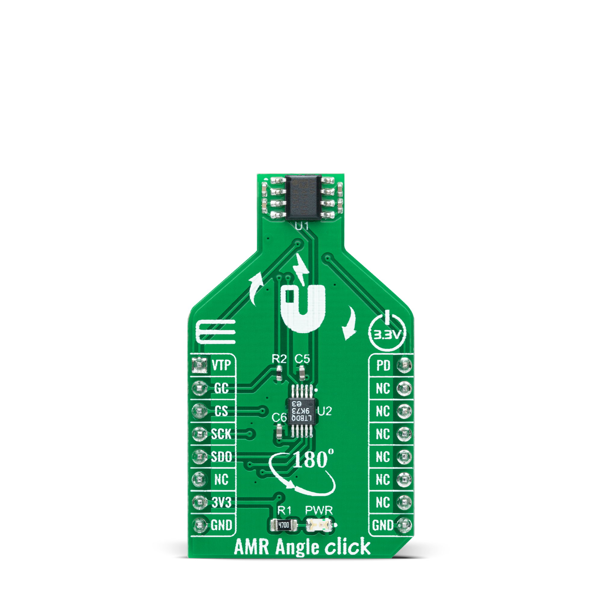
AMR Angle Click
Dev. board
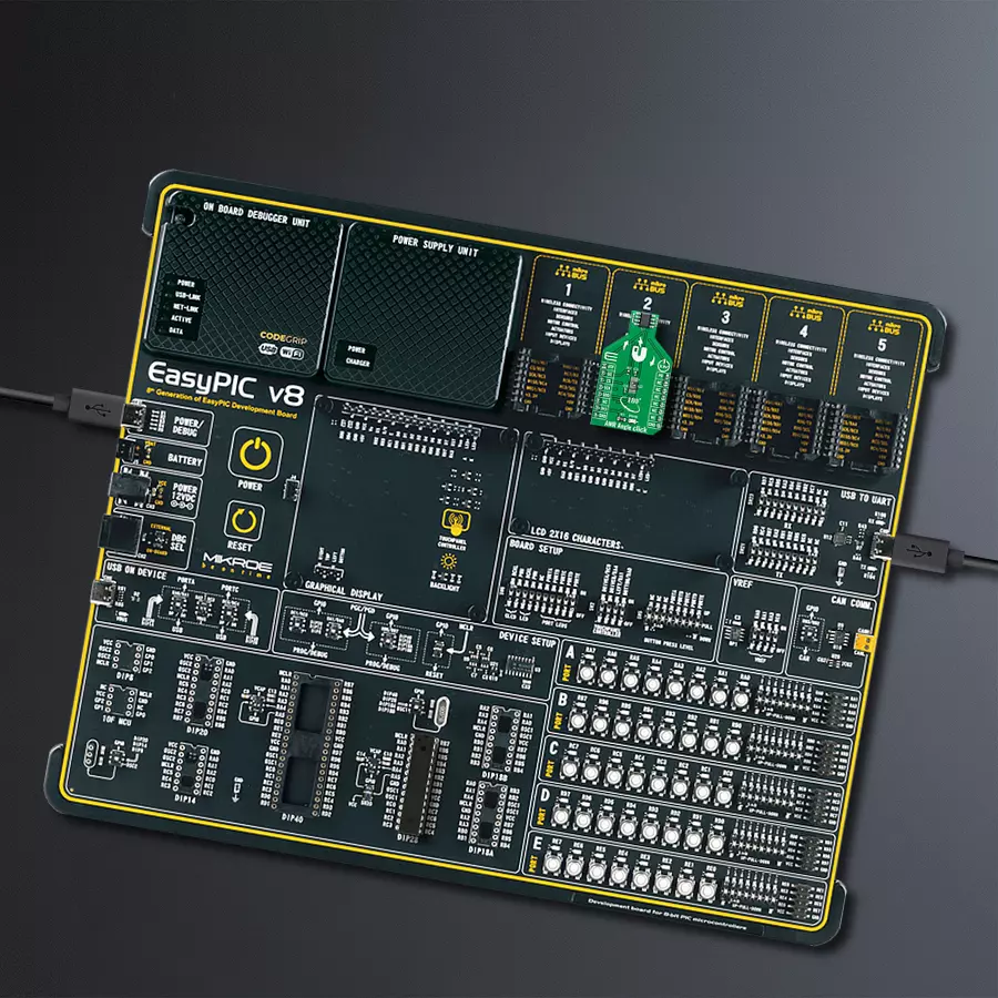
EasyPIC v8
Compiler
NECTO Studio
MCU
PIC18F26K80
Utilize this solution for precise and contactless absolute position measurement, magnetic angular position sensing, actuator control, and versatile positioning applications
A
A
Hardware Overview
How does it work?
AMR Angle Click is based on the ADA4571, an anisotropic magnetoresistive (AMR) sensor with integrated signal conditioning amplifiers, ADC drivers, and a temperature sensor for temperature compensation from Analog Devices. It produces two analog outputs that indicate the surrounding magnetic field's angular position. It comprises two dies within one package, an AMR sensor, and a fixed gain instrumentation amplifier, with G=40 nominally. It provides better than 0.2° angular accuracy over 180° and linear accuracy of 2mil (0.002 inches) over a 0.5-inch range, depending on the used magnet's size. The ADA4571 contains two Wheatstone bridges at a relative angle of 45° to one another. A rotating magnetic field in the x-y sensor plane delivers two sinusoidal output signals with the double frequency of the angle between the sensor and magnetic field direction. Within
a homogeneous field in the x-y plane, the output signals are independent of the physical placement in the z-direction (air gap). The AMR Angle Click communicates with MCU through the 3-Wire SPI serial interface using the LTC1407, 12-bit 3MSPS ADC with two 1.5MSPS simultaneously sampled differential inputs from Analog Devices. The LTC1407 samples both sensor channels simultaneously using an SPI interface, allowing access to both channels on one data line. Besides, it possesses additional functionality routed on some GPIO pins, such as Power-Down mode, Gain control, and temperature monitoring. The power-down feature labeled PD and routed on the PWM pin of the mikroBUS™ socket shuts down the device. It sets its outputs to a high impedance to avoid current consumption, while the VTEMP routed on the AN pin can be used for temperature
monitoring or calibration purposes. Gain control, labeled as GC and routed on the RST pin of the mikroBUS™ socket, activates by switching this pin to a high level. In this mode, the AMR sensor amplitude outputs are compensated to reduce temperature variation, which results in higher and controlled output voltage levels. It can also be used as a sensor self-diagnostic feature by comparing the sine and cosine amplitude outputs when enabled and disabled, such as radius check. This Click board™ can be operated only with a 3.3V logic voltage level. The board must perform appropriate logic voltage level conversion before using MCUs with different logic levels. Also, it comes equipped with a library containing functions and an example code that can be used as a reference for further development.

Features overview
Development board
EasyPIC v8 is a development board specially designed for the needs of rapid development of embedded applications. It supports many high pin count 8-bit PIC microcontrollers from Microchip, regardless of their number of pins, and a broad set of unique functions, such as the first-ever embedded debugger/programmer. The development board is well organized and designed so that the end-user has all the necessary elements, such as switches, buttons, indicators, connectors, and others, in one place. Thanks to innovative manufacturing technology, EasyPIC v8 provides a fluid and immersive working experience, allowing access anywhere and under any
circumstances at any time. Each part of the EasyPIC v8 development board contains the components necessary for the most efficient operation of the same board. In addition to the advanced integrated CODEGRIP programmer/debugger module, which offers many valuable programming/debugging options and seamless integration with the Mikroe software environment, the board also includes a clean and regulated power supply module for the development board. It can use a wide range of external power sources, including a battery, an external 12V power supply, and a power source via the USB Type-C (USB-C) connector.
Communication options such as USB-UART, USB DEVICE, and CAN are also included, including the well-established mikroBUS™ standard, two display options (graphical and character-based LCD), and several different DIP sockets. These sockets cover a wide range of 8-bit PIC MCUs, from the smallest PIC MCU devices with only eight up to forty pins. EasyPIC v8 is an integral part of the Mikroe ecosystem for rapid development. Natively supported by Mikroe software tools, it covers many aspects of prototyping and development thanks to a considerable number of different Click boards™ (over a thousand boards), the number of which is growing every day.

Microcontroller Overview
MCU Card / MCU
Architecture
PIC
MCU Memory (KB)
64
Silicon Vendor
Microchip
Pin count
28
RAM (Bytes)
3648
Used MCU Pins
mikroBUS™ mapper
Take a closer look
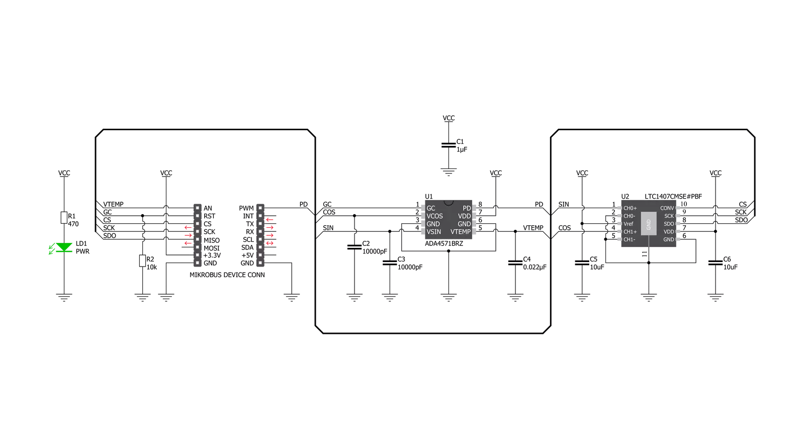
Click board™ Schematic
Step by step
Project assembly

Start by selecting your development board and Click board™. Begin with the EasyPIC v8 as your development board.


Software Support
Library Description
This library contains API for AMR Angle Click driver.
Key functions:
amrangle_angle_read- This function reads an angle in degreesamrangle_read_vtp_temp- This function returns calculated temperature using vtp pin voltageamrangle_gain_control_mode- This function sets the gain control mode pin which is used to compensate the sensor amplitude output for reduction of temperature variation.
Open Source
Code example
The complete application code and a ready-to-use project are available through the NECTO Studio Package Manager for direct installation in the NECTO Studio. The application code can also be found on the MIKROE GitHub account.
/*!
 * @file main.c
 * @brief AMRAngle Click example
 *
 * # Description
 * This demo application shows the performance of AMR Angle
 * Click by reading and presenting the temperature and angle
 * results on the UART log.
 *
 * The demo application is composed of two sections :
 *
 * ## Application Init
 * Starts up the UART LOG, SPI and ADC drivers. Performs the
 * default settings like setting the adc vref, resolution and
 * gpio pins.
 *
 * ## Application Task
 * The application task consists of reading the temperature
 * and angle data from the sensor and sending that data to the
 * UART log every second.
 *
 * @author Stefan Nikolic
 *
 */

#include "board.h"
#include "log.h"
#include "amrangle.h"

static amrangle_t amrangle;
static log_t logger;

static float temperature_res;
static float angle_res;

void application_init ( void ) {
    log_cfg_t log_cfg;              /**< Logger config object. */
    amrangle_cfg_t amrangle_cfg;    /**< Click config object. */

    /**
     * Logger initialization.
     * Default baud rate: 115200
     * Default log level: LOG_LEVEL_DEBUG
     * @note If USB_UART_RX and USB_UART_TX
     * are defined as HAL_PIN_NC, you will
     * need to define them manually for log to work.
     * See @b LOG_MAP_USB_UART macro definition for detailed explanation.
     */
    LOG_MAP_USB_UART( log_cfg );
    log_init( &logger, &log_cfg );
    log_info( &logger, " Application Init " );

    // Click initialization.

    amrangle_cfg_setup( &amrangle_cfg, AMRANGLE_ARM_TOOLCHAIN );  // Change when switching profile
    AMRANGLE_MAP_MIKROBUS( amrangle_cfg, MIKROBUS_1 );
    err_t init_flag = amrangle_init( &amrangle, &amrangle_cfg );
    if ( init_flag == SPI_MASTER_ERROR ) {
        log_error( &logger, " Application Init Error. " );
        log_info( &logger, " Please, run program again... " );

        for ( ; ; );
    }

    amrangle_default_cfg( &amrangle );
    Delay_ms ( 500 );
    log_info( &logger, " Application Task " );
}

void application_task ( void ) {
    temperature_res = amrangle_read_vtp_temp( &amrangle );
    angle_res = amrangle_angle_read( &amrangle );
    log_printf( &logger, " Temperature: %.2f C\r\n", temperature_res );
    log_printf( &logger, " Angle: %.2f degrees\r\n", angle_res );
    log_printf( &logger, " --------------------------\r\n" );
    Delay_ms ( 1000 );
}

int main ( void )
{
    /* Do not remove this line or clock might not be set correctly. */
    #ifdef PREINIT_SUPPORTED
    preinit();
    #endif

    application_init( );

    for ( ; ; )
    {
        application_task( );
    }

    return 0;
}

// ------------------------------------------------------------------------ END
Additional Support
Resources
Category:Magnetic


