Measure barometric pressure and temperature with high accuracy with ENS220 and PIC18F2455
Add environmental sensing capabilities to a wide range of electronic projects

Published Feb 22, 2024
Click board™
Barometer 9 Click
Dev. board
EasyPIC v8
Compiler
NECTO Studio
MCU
PIC18F2455
Create sophisticated, location-aware devices, particularly in the fields of activity tracking, indoor navigation, and environmental monitoring
A
A
Hardware Overview
How does it work?
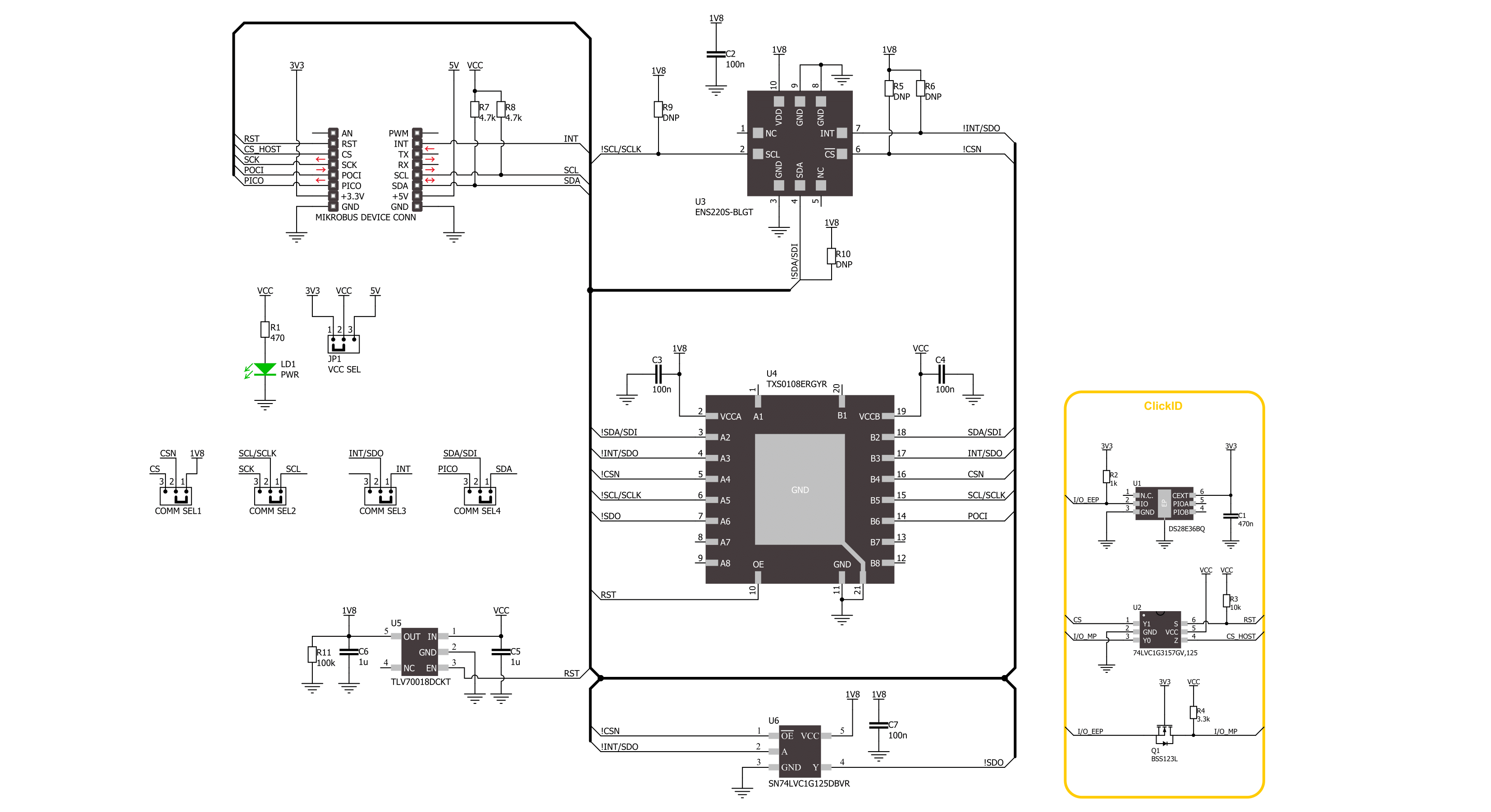
Barometer 9 Click is based on the ENS220, a state-of-the-art barometric pressure and temperature sensor from ScioSense for applications such as activity tracking and indoor navigation/localization. This sensor stands out for its ultra-low power consumption and high accuracy, offering a dual-mode communication interface that can operate through digital I2C or SPI interfaces. Embedded within a CMOS ASIC, the ENS220's capacitive pressure sensor facilitates a compact package size while ensuring robust resistance to environmental changes. The integration of a capacitive read-out mechanism contributes to its minimal power usage. It boasts a high sensitivity to pressure and incorporates an ultra-low noise 24-bit ADC converter, minimizing pressure noise significantly. The sensor also includes a precision temperature sensor, providing stable, temperature-compensated pressure readings with quick response times. Key
features of the ENS220 include a pressure range from 300 to 1200hPa, exceptional absolute accuracy within ±0.5hPa, and relative accuracy of ±0.025hPa, which translates to an altitude resolution of around 20cm. Its ultra-low pressure noise of 0.1Pa RMS at a 2Hz sampling rate and the ability to adjust the sampling rate up to 1kHz, achieving 0.9 Pa RMS, is also noteworthy. Additionally, it delivers temperature measurements with an accuracy of ±0.1K and a resolution of 8mK.
Barometer 9 Click offers flexibility through its support for both SPI and I2C interfaces, selectable via the COMM SEL jumpers. By default, the I2C interface is active, supporting Fast mode operation up to 400kHz, whereas the SPI mode accommodates clock frequencies up to 1MHz. The sensor's interrupt feature is a significant addition, enabling it to alert the host processor about specific events, such as pressure thresholds, through the
INT pin, optimizing for ultra-low power consumption scenarios. The ENS220 operates optimally at 1.8V, a power supply level provided by the TLV700, a low-dropout (LDO) regulator from Texas Instruments, sourced directly from the selected mikroBUS™ socket's power rail. Because the ENS220's power supply is 1.8V, this board also facilitates appropriate logic level conversion via the TXS0108E voltage level translator from Texas Instruments. This Click board™ can operate with either 3.3V or 5V logic voltage levels selected via the VCC SEL jumper. This way, both 3.3V and 5V capable MCUs can use the communication lines properly. Also, this Click board™ comes equipped with a library containing easy-to-use functions and an example code that can be used as a reference for further development.

Features overview
Development board
EasyPIC v8 is a development board specially designed for the needs of rapid development of embedded applications. It supports many high pin count 8-bit PIC microcontrollers from Microchip, regardless of their number of pins, and a broad set of unique functions, such as the first-ever embedded debugger/programmer. The development board is well organized and designed so that the end-user has all the necessary elements, such as switches, buttons, indicators, connectors, and others, in one place. Thanks to innovative manufacturing technology, EasyPIC v8 provides a fluid and immersive working experience, allowing access anywhere and under any
circumstances at any time. Each part of the EasyPIC v8 development board contains the components necessary for the most efficient operation of the same board. In addition to the advanced integrated CODEGRIP programmer/debugger module, which offers many valuable programming/debugging options and seamless integration with the Mikroe software environment, the board also includes a clean and regulated power supply module for the development board. It can use a wide range of external power sources, including a battery, an external 12V power supply, and a power source via the USB Type-C (USB-C) connector.
Communication options such as USB-UART, USB DEVICE, and CAN are also included, including the well-established mikroBUS™ standard, two display options (graphical and character-based LCD), and several different DIP sockets. These sockets cover a wide range of 8-bit PIC MCUs, from the smallest PIC MCU devices with only eight up to forty pins. EasyPIC v8 is an integral part of the Mikroe ecosystem for rapid development. Natively supported by Mikroe software tools, it covers many aspects of prototyping and development thanks to a considerable number of different Click boards™ (over a thousand boards), the number of which is growing every day.

Microcontroller Overview
MCU Card / MCU

Architecture
PIC
MCU Memory (KB)
24
Silicon Vendor
Microchip
Pin count
28
RAM (Bytes)
2048
Used MCU Pins
mikroBUS™ mapper
Take a closer look
Click board™ Schematic
Step by step
Project assembly

Start by selecting your development board and Click board™. Begin with the EasyPIC v8 as your development board.


Software Support
Library Description
This library contains API for Barometer 9 Click driver.
Key functions:
barometer9_read_part_id- This function is used to read a Device ID of Barometer 9 Clickbarometer9_get_temperature- This function is used to read a temperature of Barometer 9 Click in degree of Celsiusbarometer9_get_pressure- This function is used to read a pressure of Barometer 9 Click in Pascals
Open Source
Code example
The complete application code and a ready-to-use project are available through the NECTO Studio Package Manager for direct installation in the NECTO Studio. The application code can also be found on the MIKROE GitHub account.
/*!
 * @file main.c
 * @brief Barometer 9 Click example
 *
 * # Description
 * This example demonstrates the use of  Barometer 9  Click board
 * by reading and displaying the pressure and temperature measurements.
 *
 * The demo application is composed of two sections :
 *
 * ## Application Init
 * The initialization of I2C or SPI module and log UART.
 * After driver initialization, the app sets the default configuration.
 *
 * ## Application Task
 * The demo application reads and displays the Pressure [Pa] and Temperature [degree Celsius] data.
 * Results are being sent to the UART Terminal, where you can track their changes.
 *
 * @author Stefan Ilic
 *
 */

#include "board.h"
#include "log.h"
#include "barometer9.h"

static barometer9_t barometer9;
static log_t logger;

void application_init ( void )
{
    log_cfg_t log_cfg;  /**< Logger config object. */
    barometer9_cfg_t barometer9_cfg;  /**< Click config object. */

    /**
     * Logger initialization.
     * Default baud rate: 115200
     * Default log level: LOG_LEVEL_DEBUG
     * @note If USB_UART_RX and USB_UART_TX
     * are defined as HAL_PIN_NC, you will
     * need to define them manually for log to work.
     * See @b LOG_MAP_USB_UART macro definition for detailed explanation.
     */
    LOG_MAP_USB_UART( log_cfg );
    log_init( &logger, &log_cfg );
    log_info( &logger, " Application Init " );

    // Click initialization.
    barometer9_cfg_setup( &barometer9_cfg );
    BAROMETER9_MAP_MIKROBUS( barometer9_cfg, MIKROBUS_1 );
    err_t init_flag = barometer9_init( &barometer9, &barometer9_cfg );
    if ( ( I2C_MASTER_ERROR == init_flag ) || ( SPI_MASTER_ERROR == init_flag ) )
    {
        log_error( &logger, " Communication init." );
        for ( ; ; );
    }
    Delay_ms ( 100 );

    if ( BAROMETER9_ERROR == barometer9_default_cfg ( &barometer9 ) )
    {
        log_error( &logger, " Default configuration." );
        for ( ; ; );
    }

    uint16_t device_id = 0;
    barometer9_read_part_id ( &barometer9, &device_id );
    if ( BAROMETER9_DEVICE_ID != device_id )
    {
        log_error( &logger, " Read error " );
        for ( ; ; );
    }
    else
    {
        log_printf( &logger, " Device ID: 0x%.4X \r\n", device_id );
    }

    log_info( &logger, " Application Task " );
}

void application_task ( void )
{
    float temperature = 0;
    float pressure = 0;

    barometer9_get_temperature( &barometer9, &temperature );
    barometer9_get_pressure( &barometer9, &pressure );
    log_printf( &logger, " Temperature: %.2f C \r\n Pressure %.3f Pa \r\n", temperature, pressure );
    log_printf( &logger, " - - - - - - - - - - \r\n" );
    Delay_ms ( 1000 );
}

int main ( void )
{
    /* Do not remove this line or clock might not be set correctly. */
    #ifdef PREINIT_SUPPORTED
    preinit();
    #endif

    application_init( );

    for ( ; ; )
    {
        application_task( );
    }

    return 0;
}

// ------------------------------------------------------------------------ END


