Chart your course with utmost precision using ZED-F9P and PIC18F2553
The art of pinpoint accuracy
Published Nov 01, 2023
Click board™
GNSS RTK Click
Dev. board
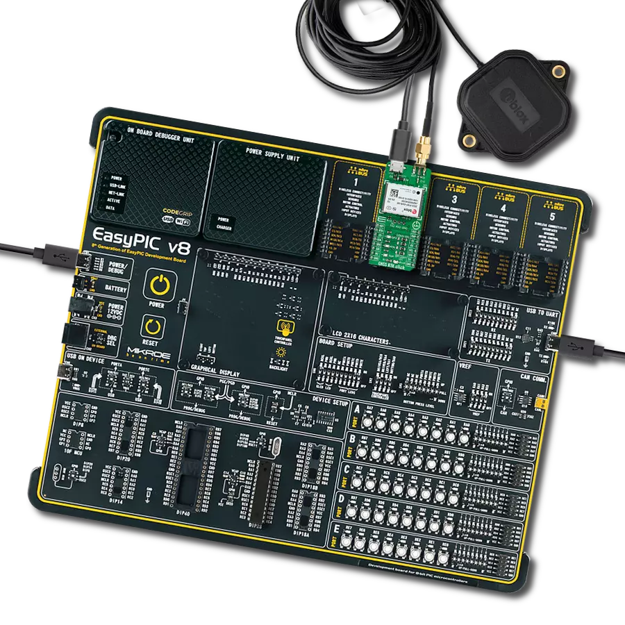
EasyPIC v8
Compiler
NECTO Studio
MCU
PIC18F2553
Step into a realm of unparalleled precision with our multi-band GNSS module, seamlessly integrated with cutting-edge multi-band Real Time Kinematics (RTK) technology. Unlock centimeter-level accuracy that revolutionizes the way we navigate and map the world.
A
A
Hardware Overview
How does it work?
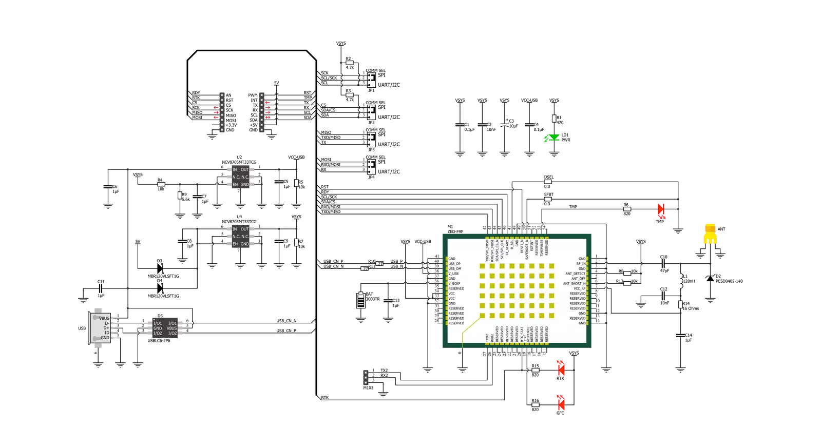
GNSS RTK Click is based on the ZED-F9P, a multi-band GNSS module with integrated multi-band RTK technology offering centimeter-level accuracy from U-blox. This GNSS receiver can receive and track multiple GNSS constellations. Thanks to the multi-band RF front-end architecture, all four major GNSS constellations (GPS, GLONASS, Galileo, and BeiDou) plus SBAS and QZSS satellites can be received concurrently. Combining GNSS signals from multiple frequency bands (L1/L2/L5) and RTK technology allows the ZED-F9P to achieve centimeter-level accuracy in seconds. Receiving more satellite signals at any given time maximizes the availability of centimeter-level accuracy even in challenging environments such as cities. The ZED-F9P has built-in support for standard RTCM corrections, routed on the additional header, unpopulated by default, and available as an optional standalone RTCM input interface that can not be used as a host interface. It also ensures the security of positioning and navigation information using secure interfaces and advanced jamming and spoofing detection technologies. GNSS RTK Click communicates with MCU using the UART interface at 9600 bps as its default communication protocol with the option for the users to use other interfaces, such as SPI and I2C if they want to configure the module and write the library by themselves. The interface
selection between UART/SPI can be performed by positioning SMD jumpers labeled COMM SEL to an appropriate position. When selecting the SPI communication, with the correct selection of the COMM SEL jumper, it is necessary to set the jumper to DSEL to configure the interface pins as SPI. In the default state, the jumper labeled as DSEL is unpopulated. The receiver also can enter a safe boot mode. If the jumper labeled SFBT is populated and the SAFEBOOT pin is low at Power-Up, the receiver starts in safe boot mode, and GNSS operation is disabled. The USB interface, compatible with the USB version 2.0 FS (Full Speed, 12 Mbit/s), can be used for communication as an alternative to the UART. The USB port can be used as a power supply if you need the Click board™ to be a standalone device. In the case of the main supply failure, the module can use a backup supply voltage from a connected battery. Backup voltage supplies the real-time clock and battery-backed RAM and enables all relevant data to be saved in the backup RAM to allow a hot or warm start later. In addition to these features, it also has several GPIO pins. RDY pin routed to the AN pin of the mikroBUS™ socket is used as a communication indicator when bytes are ready to be transmitted, the RST pin routed on the PWM pin of the mikroBUS™ socket provides the ability to reset the receiver, and the TMP pin, with LED
indicator, routed on the INT pin of the mikroBUS™ socket provides clock pulses with configurable duration and frequency. RTK pin routed on the RST pin of the mikroBUS™ socket, alongside the LED indicator labeled RTK, indicates the RTK positioning status. When the LED blinks, it indicates that a valid stream of RTCM messages is being received, but no RTK fixed mode has been achieved. When the LED is constantly lit, the LED indicates that RTK mode has been achieved. It also has another LED indicator labeled as GDC that indicates the current geofence status of whether the receiver is inside any active areas. For example, this feature can be used to wake up a sleeping host when a defined geofence condition is reached. GNSS RTK Click possesses the SMA antenna connector, and it can be used for connecting the appropriate antenna that Mikroe has in its offer, such as GPS Active External Antenna. This antenna is an excellent choice for all GSM/GPRS applications with a frequency range of 1595.42 ± 25MHz. This Click board™ can be operated only with a 5V logic voltage level. The board must perform appropriate logic voltage level conversion before using MCUs with different logic levels. Also, it comes equipped with a library containing functions and an example code that can be used as a reference for further development.

Features overview
Development board
EasyPIC v8 is a development board specially designed for the needs of rapid development of embedded applications. It supports many high pin count 8-bit PIC microcontrollers from Microchip, regardless of their number of pins, and a broad set of unique functions, such as the first-ever embedded debugger/programmer. The development board is well organized and designed so that the end-user has all the necessary elements, such as switches, buttons, indicators, connectors, and others, in one place. Thanks to innovative manufacturing technology, EasyPIC v8 provides a fluid and immersive working experience, allowing access anywhere and under any
circumstances at any time. Each part of the EasyPIC v8 development board contains the components necessary for the most efficient operation of the same board. In addition to the advanced integrated CODEGRIP programmer/debugger module, which offers many valuable programming/debugging options and seamless integration with the Mikroe software environment, the board also includes a clean and regulated power supply module for the development board. It can use a wide range of external power sources, including a battery, an external 12V power supply, and a power source via the USB Type-C (USB-C) connector.
Communication options such as USB-UART, USB DEVICE, and CAN are also included, including the well-established mikroBUS™ standard, two display options (graphical and character-based LCD), and several different DIP sockets. These sockets cover a wide range of 8-bit PIC MCUs, from the smallest PIC MCU devices with only eight up to forty pins. EasyPIC v8 is an integral part of the Mikroe ecosystem for rapid development. Natively supported by Mikroe software tools, it covers many aspects of prototyping and development thanks to a considerable number of different Click boards™ (over a thousand boards), the number of which is growing every day.

Microcontroller Overview
MCU Card / MCU

Architecture
PIC
MCU Memory (KB)
32
Silicon Vendor
Microchip
Pin count
28
RAM (Bytes)
2048
You complete me!
Accessories
GNSS Active External Antenna is a unique multi-band type of antenna coming from u-Blox that is the perfect selection for high precision GNSS applications, which require highly accurate location abilities such as RTK. The ANN-MB-00 is a multi-band (L1, L2/E5b/B2I) active GNSS antenna with a 5m cable and SMA connector. The antenna supports GPS, GLONASS, Galileo, and BeiDou and includes a high-performance multi-band RHCP dual-feed patch antenna element, a built-in high-gain LNA with SAW pre-filtering, and a 5 m antenna cable with SMA connector, and is waterproof.

Used MCU Pins
mikroBUS™ mapper
Take a closer look
Click board™ Schematic
Step by step
Project assembly

Start by selecting your development board and Click board™. Begin with the EasyPIC v8 as your development board.


Track your results in real time
Application Output
1. Application Output - In Debug mode, the 'Application Output' window enables real-time data monitoring, offering direct insight into execution results. Ensure proper data display by configuring the environment correctly using the provided tutorial.

2. UART Terminal - Use the UART Terminal to monitor data transmission via a USB to UART converter, allowing direct communication between the Click board™ and your development system. Configure the baud rate and other serial settings according to your project's requirements to ensure proper functionality. For step-by-step setup instructions, refer to the provided tutorial.

3. Plot Output - The Plot feature offers a powerful way to visualize real-time sensor data, enabling trend analysis, debugging, and comparison of multiple data points. To set it up correctly, follow the provided tutorial, which includes a step-by-step example of using the Plot feature to display Click board™ readings. To use the Plot feature in your code, use the function: plot(*insert_graph_name*, variable_name);. This is a general format, and it is up to the user to replace 'insert_graph_name' with the actual graph name and 'variable_name' with the parameter to be displayed.

Software Support
Library Description
This library contains API for GNSS RTK Click driver.
Key functions:
gnssrtk_reset_device- This function resets the device by toggling the RST pingnssrtk_generic_read- This function reads a desired number of data bytes from the module.gnssrtk_parse_gngga- This function parses the GNGGA data from the read response buffer.
Open Source
Code example
The complete application code and a ready-to-use project are available through the NECTO Studio Package Manager for direct installation in the NECTO Studio. The application code can also be found on the MIKROE GitHub account.
/*!
 * @file main.c
 * @brief GNSS RTK Click example
 *
 * # Description
 * This example demonstrates the use of GNSS RTK Click by reading and displaying
 * the GNSS coordinates.
 *
 * The demo application is composed of two sections :
 *
 * ## Application Init
 * Initializes the driver and resets the Click board.
 *
 * ## Application Task
 * Reads the received data, parses the GNGGA info from it, and once it receives the position fix
 * it will start displaying the coordinates on the USB UART.
 *
 * ## Additional Function
 * - static void gnssrtk_clear_app_buf ( void )
 * - static err_t gnssrtk_process ( gnssrtk_t *ctx )
 * - static void gnssrtk_parser_application ( char *rsp )
 *
 * @author Stefan Filipovic
 *
 */

#include "board.h"
#include "log.h"
#include "gnssrtk.h"

#define PROCESS_BUFFER_SIZE 300

static gnssrtk_t gnssrtk;
static log_t logger;

static char app_buf[ PROCESS_BUFFER_SIZE ] = { 0 };
static int32_t app_buf_len = 0;

/**
 * @brief GNSS RTK clearing application buffer.
 * @details This function clears memory of application buffer and reset its length.
 * @return None.
 * @note None.
 */
static void gnssrtk_clear_app_buf ( void );

/**
 * @brief GNSS RTK data reading function.
 * @details This function reads data from device and concatenates data to application buffer.
 * @param[in] ctx : Click context object.
 * See #gnssrtk_t object definition for detailed explanation.
 * @return @li @c  0 - Read some data.
 *         @li @c -1 - Nothing is read or Application buffer overflow.
 * See #err_t definition for detailed explanation.
 * @note None.
 */
static err_t gnssrtk_process ( gnssrtk_t *ctx );

/**
 * @brief GNSS RTK parser application.
 * @param[in] rsp Response buffer.
 * @details This function logs GNSS data on the USB UART.
 * @return None.
 * @note None.
 */
static void gnssrtk_parser_application ( char *rsp );

void application_init ( void )
{
    log_cfg_t log_cfg;  /**< Logger config object. */
    gnssrtk_cfg_t gnssrtk_cfg;  /**< Click config object. */

    /**
     * Logger initialization.
     * Default baud rate: 115200
     * Default log level: LOG_LEVEL_DEBUG
     * @note If USB_UART_RX and USB_UART_TX
     * are defined as HAL_PIN_NC, you will
     * need to define them manually for log to work.
     * See @b LOG_MAP_USB_UART macro definition for detailed explanation.
     */
    LOG_MAP_USB_UART( log_cfg );
    log_init( &logger, &log_cfg );
    log_info( &logger, " Application Init " );

    // Click initialization.
    gnssrtk_cfg_setup( &gnssrtk_cfg );
    GNSSRTK_MAP_MIKROBUS( gnssrtk_cfg, MIKROBUS_1 );
    err_t init_flag = gnssrtk_init( &gnssrtk, &gnssrtk_cfg );
    if ( ( UART_ERROR == init_flag ) || ( I2C_MASTER_ERROR == init_flag ) || ( SPI_MASTER_ERROR == init_flag ) )
    {
        log_error( &logger, " Communication init." );
        for ( ; ; );
    }

    log_info( &logger, " Application Task " );
}

void application_task ( void )
{
    gnssrtk_process( &gnssrtk );
    if ( app_buf_len > ( sizeof ( GNSSRTK_RSP_GNGGA ) + GNSSRTK_GNGGA_ELEMENT_SIZE ) )
    {
        gnssrtk_parser_application( app_buf );
    }
}

int main ( void )
{
    /* Do not remove this line or clock might not be set correctly. */
    #ifdef PREINIT_SUPPORTED
    preinit();
    #endif

    application_init( );

    for ( ; ; )
    {
        application_task( );
    }

    return 0;
}

static void gnssrtk_clear_app_buf ( void )
{
    memset( app_buf, 0, app_buf_len );
    app_buf_len = 0;
}

static err_t gnssrtk_process ( gnssrtk_t *ctx )
{
    int32_t rx_size = 0;
    char rx_buf[ PROCESS_BUFFER_SIZE ] = { 0 };
    if ( GNSSRTK_DRV_SEL_UART == ctx->drv_sel )
    {
        rx_size = gnssrtk_generic_read( ctx, rx_buf, PROCESS_BUFFER_SIZE );
    }
    else if ( ( GNSSRTK_DRV_SEL_I2C == ctx->drv_sel ) || ( GNSSRTK_DRV_SEL_SPI == ctx->drv_sel ) )
    {
        if ( GNSSRTK_OK == gnssrtk_generic_read( ctx, rx_buf, 1 ) )
        {
            if ( GNSSRTK_DUMMY != rx_buf[ 0 ] )
            {
                rx_size = 1;
            }
        }
    }
    if ( rx_size > 0 )
    {
        int32_t buf_cnt = 0;
        if ( ( app_buf_len + rx_size ) > PROCESS_BUFFER_SIZE )
        {
            gnssrtk_clear_app_buf(  );
            return GNSSRTK_ERROR;
        }
        else
        {
            buf_cnt = app_buf_len;
            app_buf_len += rx_size;
        }
        for ( int32_t rx_cnt = 0; rx_cnt < rx_size; rx_cnt++ )
        {
            if ( rx_buf[ rx_cnt ] )
            {
                app_buf[ ( buf_cnt + rx_cnt ) ] = rx_buf[ rx_cnt ];
            }
            else
            {
                app_buf_len--;
                buf_cnt--;
            }
        }
        return GNSSRTK_OK;
    }
    return GNSSRTK_ERROR;
}

static void gnssrtk_parser_application ( char *rsp )
{
    char element_buf[ 100 ] = { 0 };
    if ( GNSSRTK_OK == gnssrtk_parse_gngga( rsp, GNSSRTK_GNGGA_LATITUDE, element_buf ) )
    {
        static uint8_t wait_for_fix_cnt = 0;
        if ( strlen( element_buf ) > 0 )
        {
            log_printf( &logger, "\r\n Latitude: %.2s degrees, %s minutes \r\n", element_buf, &element_buf[ 2 ] );
            gnssrtk_parse_gngga( rsp, GNSSRTK_GNGGA_LONGITUDE, element_buf );
            log_printf( &logger, " Longitude: %.3s degrees, %s minutes \r\n", element_buf, &element_buf[ 3 ] );
            memset( element_buf, 0, sizeof( element_buf ) );
            gnssrtk_parse_gngga( rsp, GNSSRTK_GNGGA_ALTITUDE, element_buf );
            log_printf( &logger, " Altitude: %s m \r\n", element_buf );
            wait_for_fix_cnt = 0;
        }
        else
        {
            if ( wait_for_fix_cnt % 5 == 0 )
            {
                log_printf( &logger, " Waiting for the position fix...\r\n\n" );
                wait_for_fix_cnt = 0;
            }
            wait_for_fix_cnt++;
        }
        gnssrtk_clear_app_buf(  );
    }
}

// ------------------------------------------------------------------------ END


