Unlock the world of accurate navigation with NEO-D9S-00B and PIC18F2553
Elevate accuracy in every corner of the globe
Published Nov 01, 2023
Click board™
LBAND RTK Click
Dev. board
EasyPIC v8
Compiler
NECTO Studio
MCU
PIC18F2553
Experience the seamless global reach and accuracy convergence through our L-Band GNSS corrections solution. With corrections at your fingertips, you can navigate confidently, knowing precision is no longer a limitation.
A
A
Hardware Overview
How does it work?
LBAND RTK Click is based on the NEO-D9S-00B, a satellite data receiver for L-band correction broadcast from u-blox, which can be configured for use with various correction services. Operating in a frequency range from 1525MHz to 1559MHz, the NEO-D9S-00B decodes the satellite transmission and outputs a correction stream, enabling a high-precision GNSS receiver to reach accuracies down to centimeter level. An independent stream of correction data, delivered over satellite L-band, ensures high availability of position output. Simultaneously, it reduces dependence on a cellular connection for the correction service provided over IP. Besides, it implements advanced security features such as signature and anti-jamming mechanisms. In addition to accessing the broadcast data stream, the NEO-D9S-00B also eliminates the need for a dedicated delivery channel per user, making it flexible for different markets and applications. It is configurable for use with correction data of various providers and service levels, ensuring precision in multiple regions globally and coverage across continents. This Click board™ can be easily integrated with other GNSS receivers from the u-blox F9 platform, such as GNSS RTK Click boards™
from our offer, providing a complete solution built with less design effort. LBAND RTK Click communicates with the host MCU using the UART interface at 115200bps as its default communication protocol but also has other interfaces, such as SPI and I2C. The interface is selected by positioning SMD jumpers labeled COMM SEL in an appropriate position. When choosing the SPI communication, with the correct selection of the COMM SEL jumpers, it is also necessary to populate the DSEL jumper to configure the interface pins as SPI. In the default state, the jumper labeled as DSEL is unpopulated. In the case of using only this Click board™ alone via the I2C interface, it is necessary to populate I2C pull-up resistors (R2 and R3). Remove these resistors when using LBAND RTK with other GNSS RTK boards. An additional header holds an optional UART interface, which can provide correction data directly to a GNSS receiver. The USB interface, compatible with USB version 2.0 (Full Speed, 12 Mbit/s), can be used for communication as an alternative to the UART. Also, the USB port can be used as an additional power supply if you need the Click board™ to be a standalone device. In this case, the main module
supply is provided by an onboard regulator, the NCV8705, providing the necessary 3.3V for its proper operation. The receiver also can enter a Safe-Boot mode. When the jumper labeled SFBT is populated, the receiver starts in Safe-Boot mode, and the L-band operation is disabled. During Safe-Boot mode, only the main UART interface is possible. In addition to these features, this board also uses several mikroBUS™ pins. EIN pin routed to the AN pin of the mikroBUS™ socket is used as an external interrupt feature activated through a population of the R6 0Ω resistor. The RST pin routed on the PWM pin of the mikroBUS™ socket provides the general reset ability. LBAND RTK Click possesses the SMA antenna connector for connecting the appropriate antenna that Mikroe offers, such as the GNSS L-Band Active Antenna. This antenna easily allows positioning in space, supporting GNSS L-Band frequencies. This Click board™ can be operated only with a 5V logic voltage level. The board must perform appropriate logic voltage level conversion before using MCUs with different logic levels. However, the Click board™ comes equipped with a library containing functions and an example code that can be used as a reference for further development.

Features overview
Development board
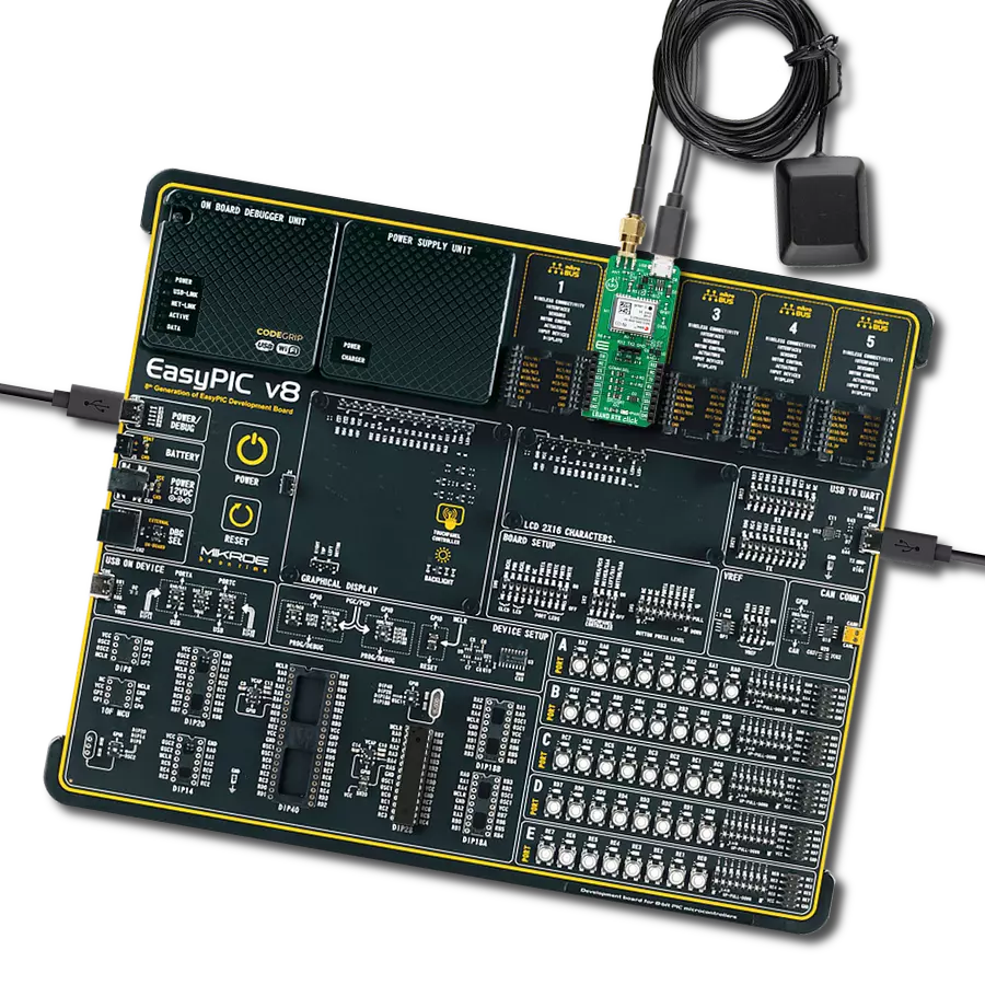
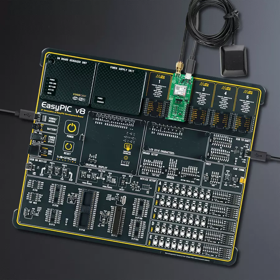
EasyPIC v8 is a development board specially designed for the needs of rapid development of embedded applications. It supports many high pin count 8-bit PIC microcontrollers from Microchip, regardless of their number of pins, and a broad set of unique functions, such as the first-ever embedded debugger/programmer. The development board is well organized and designed so that the end-user has all the necessary elements, such as switches, buttons, indicators, connectors, and others, in one place. Thanks to innovative manufacturing technology, EasyPIC v8 provides a fluid and immersive working experience, allowing access anywhere and under any
circumstances at any time. Each part of the EasyPIC v8 development board contains the components necessary for the most efficient operation of the same board. In addition to the advanced integrated CODEGRIP programmer/debugger module, which offers many valuable programming/debugging options and seamless integration with the Mikroe software environment, the board also includes a clean and regulated power supply module for the development board. It can use a wide range of external power sources, including a battery, an external 12V power supply, and a power source via the USB Type-C (USB-C) connector.
Communication options such as USB-UART, USB DEVICE, and CAN are also included, including the well-established mikroBUS™ standard, two display options (graphical and character-based LCD), and several different DIP sockets. These sockets cover a wide range of 8-bit PIC MCUs, from the smallest PIC MCU devices with only eight up to forty pins. EasyPIC v8 is an integral part of the Mikroe ecosystem for rapid development. Natively supported by Mikroe software tools, it covers many aspects of prototyping and development thanks to a considerable number of different Click boards™ (over a thousand boards), the number of which is growing every day.

Microcontroller Overview
MCU Card / MCU

Architecture
PIC
MCU Memory (KB)
32
Silicon Vendor
Microchip
Pin count
28
RAM (Bytes)
2048
You complete me!
Accessories
GNSS L-Band Active Antenna (LBAND01D-S6-00) is an active patch 50Ω antenna from Inpaq Technology that supports GNSS L-Band (frequency range from 1525 up to 1559MHz) applications. It offers excellent performance with its high gain and efficiency for tracking, fleet management, navigation, and many other tracking applications. The magnetic mounting type antenna, with dimensions of 37.5x34.5x12.5mm, connects to the device by a 3m long cable with an SMA PLUG male connector. It provides superior performance when coupled with Click boards™ that require highly accurate location abilities such as RTK.

Used MCU Pins
mikroBUS™ mapper
Take a closer look
Click board™ Schematic

Step by step
Project assembly

Start by selecting your development board and Click board™. Begin with the EasyPIC v8 as your development board.


Track your results in real time
Application Output
1. Application Output - In Debug mode, the 'Application Output' window enables real-time data monitoring, offering direct insight into execution results. Ensure proper data display by configuring the environment correctly using the provided tutorial.

2. UART Terminal - Use the UART Terminal to monitor data transmission via a USB to UART converter, allowing direct communication between the Click board™ and your development system. Configure the baud rate and other serial settings according to your project's requirements to ensure proper functionality. For step-by-step setup instructions, refer to the provided tutorial.

3. Plot Output - The Plot feature offers a powerful way to visualize real-time sensor data, enabling trend analysis, debugging, and comparison of multiple data points. To set it up correctly, follow the provided tutorial, which includes a step-by-step example of using the Plot feature to display Click board™ readings. To use the Plot feature in your code, use the function: plot(*insert_graph_name*, variable_name);. This is a general format, and it is up to the user to replace 'insert_graph_name' with the actual graph name and 'variable_name' with the parameter to be displayed.

Software Support
Library Description
This library contains API for LBAND RTK Click driver.
Key functions:
lbandrtk_set_default_pmp_cfg- This function sets the Point to multipoint (PMP) to default configuration to RAM layerlbandrtk_get_pmp_cfg- This function reads the Point to multipoint (PMP) configuration from RAM layerlbandrtk_read_ubx_frame- This function waits for an UBX frame message to arrive and reads it.
Open Source
Code example
The complete application code and a ready-to-use project are available through the NECTO Studio Package Manager for direct installation in the NECTO Studio. The application code can also be found on the MIKROE GitHub account.
/*!
 * @file main.c
 * @brief LBAND RTK Click example
 *
 * # Description
 * This example demonstrates the use of LBAND RTK Click by setting the Point to multipoint (PMP)
 * configuration and waiting for the UBX-RXM-PMP message, then parsing it and displaying on the USB UART.
 *
 * The demo application is composed of two sections :
 *
 * ## Application Init
 * Initializes the driver, reads the module version, sets the Point to multipoint (PMP) configuration
 * (for EU center frequency by default) and then reads that config and displays on the USB UART.
 *
 * ## Application Task
 * Waits for an incoming UBX messages, reads and displays them on the USB UART. If the received message is
 * PMP data it will be parsed additionally.
 *
 * @note
 * Make sure to use a correct L-Band antenna and that it's placed outside on open-sky in order to be able to
 * receive PMP data from satellites.
 *
 * @author Stefan Filipovic
 *
 */

#include "board.h"
#include "log.h"
#include "lbandrtk.h"

static lbandrtk_t lbandrtk;
static log_t logger;

void application_init ( void )
{
    log_cfg_t log_cfg;  /**< Logger config object. */
    lbandrtk_cfg_t lbandrtk_cfg;  /**< Click config object. */

    /**
     * Logger initialization.
     * Default baud rate: 115200
     * Default log level: LOG_LEVEL_DEBUG
     * @note If USB_UART_RX and USB_UART_TX
     * are defined as HAL_PIN_NC, you will
     * need to define them manually for log to work.
     * See @b LOG_MAP_USB_UART macro definition for detailed explanation.
     */
    LOG_MAP_USB_UART( log_cfg );
    log_init( &logger, &log_cfg );
    log_info( &logger, " Application Init " );

    // Click initialization.
    lbandrtk_cfg_setup( &lbandrtk_cfg );
    LBANDRTK_MAP_MIKROBUS( lbandrtk_cfg, MIKROBUS_1 );
    if ( LBANDRTK_OK != lbandrtk_init( &lbandrtk, &lbandrtk_cfg ) )
    {
        log_error( &logger, " Communication init." );
        for ( ; ; );
    }
    Delay_ms ( 100 );

    // Read module version
    lbandrtk.frame.class_id = LBANDRTK_CLASS_ID_UBX_MON;
    lbandrtk.frame.msg_id = LBANDRTK_MSG_ID_UBX_MON_VER;
    lbandrtk.frame.payload_len = 0;
    // send poll request
    lbandrtk_write_ubx_frame ( &lbandrtk, &lbandrtk.frame );
    // read polled message
    if ( LBANDRTK_OK == lbandrtk_read_ubx_frame ( &lbandrtk, &lbandrtk.frame ) )
    {
        log_printf( &logger, " ------ MODULE VERSION ------\r\n" );
        log_printf( &logger, " SW version:\r\n %s\r\n\n", &lbandrtk.frame.payload[ 0 ] );
        log_printf( &logger, " HW version:\r\n %s\r\n\n", &lbandrtk.frame.payload[ 30 ] );
        log_printf( &logger, " Extension:\r\n" );
        for ( uint16_t cnt = 0; cnt < ( ( lbandrtk.frame.payload_len - 40 ) / 30 ); cnt++ )
        {
            log_printf( &logger, " %s\r\n", &lbandrtk.frame.payload[ 40 + cnt * 30 ] );
        }
        log_printf( &logger, " ----------------------------\r\n\n" );
    }
    Delay_ms ( 100 );

    if ( LBANDRTK_ERROR == lbandrtk_set_default_pmp_cfg ( &lbandrtk ) )
    {
        log_error( &logger, " Set default PMP configuration." );
        for ( ; ; );
    }

    lbandrtk_pmp_cfg_t pmp_cfg;
    if ( LBANDRTK_OK == lbandrtk_get_pmp_cfg ( &lbandrtk, &pmp_cfg ) )
    {
        log_printf( &logger, " ----- PMP CONFIGURATION ----\r\n" );
        log_printf( &logger, " Center frequency: %lu\r\n", pmp_cfg.center_freq );
        log_printf( &logger, " Search window: %u\r\n", pmp_cfg.search_window );
        log_printf( &logger, " Use service ID: %u\r\n", ( uint16_t ) pmp_cfg.use_service_id );
        log_printf( &logger, " Service ID: %u\r\n", pmp_cfg.service_id );
        log_printf( &logger, " Data rate: %u\r\n", pmp_cfg.data_rate );
        log_printf( &logger, " Use descrambler: %u\r\n", ( uint16_t ) pmp_cfg.use_descrambler );
        log_printf( &logger, " Descrambler init: %u\r\n", pmp_cfg.descrambler_init );
        log_printf( &logger, " Use prescrambling: %lu\r\n", ( uint16_t ) pmp_cfg.use_prescrambling );
        log_printf( &logger, " Unique word: 0x%.8LX%.8LX\r\n", pmp_cfg.unique_word_high, pmp_cfg.unique_word_low );
        log_printf( &logger, " ----------------------------\r\n\n" );
    }

    log_info( &logger, " Application Task " );
}

void application_task ( void )
{
    if ( LBANDRTK_OK == lbandrtk_read_ubx_frame ( &lbandrtk, &lbandrtk.frame ) )
    {
        if ( ( LBANDRTK_CLASS_ID_UBX_RXM == lbandrtk.frame.class_id ) && ( LBANDRTK_MSG_ID_UBX_RXM_PMP == lbandrtk.frame.msg_id ) )
        {
            log_printf( &logger, " -------- UBX-RXM-PMP -------\r\n" );
            uint16_t num_bytes_user_data = LBANDRTK_UBX_RXM_PMP_MAX_USER_DATA; // Number of bytes for user data for message version 0
            log_printf( &logger, " Version: %u\r\n", ( uint16_t ) lbandrtk.frame.payload[ 0 ] );
            log_printf( &logger, " Time tag [ms]: %lu\r\n",
                        ( ( uint32_t ) lbandrtk.frame.payload[ 7 ] << 24 ) | ( ( uint32_t ) lbandrtk.frame.payload[ 6 ] << 16 ) |
                        ( ( uint16_t ) lbandrtk.frame.payload[ 5 ] << 8 ) | lbandrtk.frame.payload[ 4 ] );
            log_printf( &logger, " Unique word: 0x%.8LX%.8LX\r\n",
                        ( ( uint32_t ) lbandrtk.frame.payload[ 15 ] << 24 ) | ( ( uint32_t ) lbandrtk.frame.payload[ 14 ] << 16 ) |
                        ( ( uint16_t ) lbandrtk.frame.payload[ 13 ] << 8 ) | lbandrtk.frame.payload[ 12 ],
                        ( ( uint32_t ) lbandrtk.frame.payload[ 11 ] << 24 ) | ( ( uint32_t ) lbandrtk.frame.payload[ 10 ] << 16 ) |
                        ( ( uint16_t ) lbandrtk.frame.payload[ 9 ] << 8 ) | lbandrtk.frame.payload[ 8 ] );
            log_printf( &logger, " Unique word bit errors: %u\r\n", ( uint16_t ) lbandrtk.frame.payload[ 19 ] );
            // Check the received message version
            if ( lbandrtk.frame.payload[ 0 ] )
            {
                log_printf( &logger, " FEC bits : %u\r\n", ( ( uint16_t ) lbandrtk.frame.payload[ 21 ] << 8 ) | lbandrtk.frame.payload[ 20 ] );
                log_printf( &logger, " Eb/N0 [dB] : %.3f\r\n", lbandrtk.frame.payload[ 22 ] * LBANDRTK_UBX_RXM_PMP_EBN0_SCALE );
            }
            else
            {
                log_printf( &logger, " FEC bits : %u\r\n", ( ( uint16_t ) lbandrtk.frame.payload[ 525 ] << 8 ) | lbandrtk.frame.payload[ 524 ] );
                log_printf( &logger, " Eb/N0 [dB] : %.3f\r\n", lbandrtk.frame.payload[ 526 ] * LBANDRTK_UBX_RXM_PMP_EBN0_SCALE );
            }
            log_printf( &logger, "\r\n Service ID : %u\r\n", ( ( uint16_t ) lbandrtk.frame.payload[ 17 ] << 8 ) | lbandrtk.frame.payload[ 16 ] );
            log_printf( &logger, " Spare byte: %u\r\n", ( uint16_t ) lbandrtk.frame.payload[ 18 ] );
            // Check the received message version
            if ( lbandrtk.frame.payload[ 0 ] )
            {
                // Get number of bytes for user data for message version 1
                num_bytes_user_data = ( ( uint16_t ) lbandrtk.frame.payload[ 3 ] << 8 ) | lbandrtk.frame.payload[ 2 ];
                if ( num_bytes_user_data > LBANDRTK_UBX_RXM_PMP_MAX_USER_DATA )
                {
                    num_bytes_user_data = LBANDRTK_UBX_RXM_PMP_MAX_USER_DATA;
                }
                log_printf( &logger, " User data bytes: %u\r\n", num_bytes_user_data );
                log_printf( &logger, " User data:\r\n" );
                for ( uint16_t cnt = 0; cnt < num_bytes_user_data; cnt++ )
                {
                    if ( 0 == ( cnt % 20 ) )
                    {
                        log_printf( &logger, "\r\n" );
                    }
                    log_printf( &logger, "%.2X ", ( uint16_t ) lbandrtk.frame.payload[ 24 + cnt ] );
                }
            }
            else
            {
                log_printf( &logger, " User data bytes: %u\r\n", num_bytes_user_data );
                log_printf( &logger, " User data:\r\n" );
                for ( uint16_t cnt = 0; cnt < num_bytes_user_data; cnt++ )
                {
                    if ( 0 == ( cnt % 20 ) )
                    {
                        log_printf( &logger, "\r\n" );
                    }
                    log_printf( &logger, " %.2X", ( uint16_t ) lbandrtk.frame.payload[ 20 + cnt ] );
                }
            }
            log_printf( &logger, "\r\n ----------------------------\r\n\n" );
            Delay_ms ( 100 );
        }
        else
        {
            log_printf( &logger, " ---- UBX FRAME RECEIVED ----\r\n" );
            log_printf( &logger, " Class ID: 0x%.2X\r\n", ( uint16_t ) lbandrtk.frame.class_id );
            log_printf( &logger, " Message ID: 0x%.2X\r\n", ( uint16_t ) lbandrtk.frame.msg_id );
            log_printf( &logger, " Payload length: %u\r\n", lbandrtk.frame.payload_len );
            log_printf( &logger, " Payload:" );
            for ( uint16_t cnt = 0; cnt < lbandrtk.frame.payload_len; cnt++ )
            {
                if ( 0 == ( cnt % 20 ) )
                {
                    log_printf( &logger, "\r\n" );
                }
                log_printf( &logger, " %.2X", ( uint16_t ) lbandrtk.frame.payload[ cnt ] );
            }
            log_printf( &logger, "\r\n ----------------------------\r\n\n" );
            Delay_ms ( 100 );
        }
    }
}

int main ( void )
{
    /* Do not remove this line or clock might not be set correctly. */
    #ifdef PREINIT_SUPPORTED
    preinit();
    #endif

    application_init( );

    for ( ; ; )
    {
        application_task( );
    }

    return 0;
}

// ------------------------------------------------------------------------ END


