Develop infrared presence and motion detection solution with STHS34PF80 and PIC18F2455
Monitoring object's black-body radiation and ambient temperature in an 80° FoV

Published Jan 16, 2024
Click board™
IR Sense 4 Click
Dev. board
EasyPIC v8
Compiler
NECTO Studio
MCU
PIC18F2455
Short-range presence and motion detection solution ideal for security systems, home automation, and smart lighting projects
A
A
Hardware Overview
How does it work?
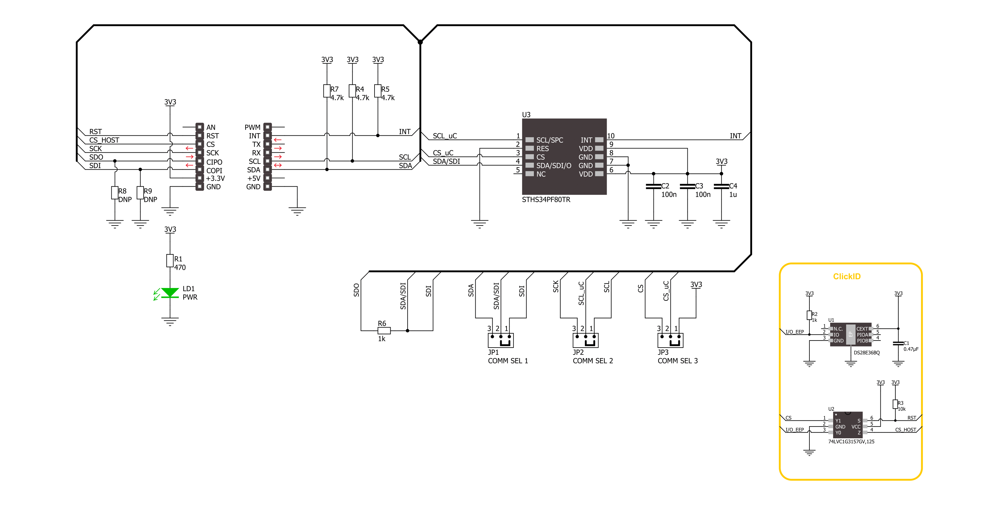
IR Sense 4 Click is based on the STHS34PF80, a low-power, high-sensitivity infrared (IR) sensor from STMicroelectronics. The sensor has a high IR sensitivity and low RMS noise, and it is factory-calibrated and temperature-compensated. The sensor itself has an integrated IR filter, has an 80-degree field of view, and operates in a wavelength of 5μm to 20μm. It measures the object’s radiation with unique TMOS technology to detect its presence or motion. When the object is inside the FoV, it is based on a matrix of floating vacuum
thermal transistors connected together and acting as a single sensing element. The sensor is split into two parts, one exposed to IR radiation and the other shielded. Differential reading between the two parts is implemented to remove the effect of sensor self-heating. IR Sense 4 Click can use a standard 2-wire I2C interface to communicate with the host MCU supporting clock frequency of up to 1MHz. It can also use a 3-wire SPI interface for the same purpose with a clock frequency of up to 10MHz. The selection can be made over the COMM SEL
jumpers. The smart processing will detect or discriminate between stationary and moving objects and assert an interrupt INT pin. This Click board™ can be operated only with a 3.3V logic voltage level. The board must perform appropriate logic voltage level conversion before using MCUs with different logic levels. Also, it comes equipped with a library containing functions and an example code that can be used as a reference for further development.

Features overview
Development board
EasyPIC v8 is a development board specially designed for the needs of rapid development of embedded applications. It supports many high pin count 8-bit PIC microcontrollers from Microchip, regardless of their number of pins, and a broad set of unique functions, such as the first-ever embedded debugger/programmer. The development board is well organized and designed so that the end-user has all the necessary elements, such as switches, buttons, indicators, connectors, and others, in one place. Thanks to innovative manufacturing technology, EasyPIC v8 provides a fluid and immersive working experience, allowing access anywhere and under any
circumstances at any time. Each part of the EasyPIC v8 development board contains the components necessary for the most efficient operation of the same board. In addition to the advanced integrated CODEGRIP programmer/debugger module, which offers many valuable programming/debugging options and seamless integration with the Mikroe software environment, the board also includes a clean and regulated power supply module for the development board. It can use a wide range of external power sources, including a battery, an external 12V power supply, and a power source via the USB Type-C (USB-C) connector.
Communication options such as USB-UART, USB DEVICE, and CAN are also included, including the well-established mikroBUS™ standard, two display options (graphical and character-based LCD), and several different DIP sockets. These sockets cover a wide range of 8-bit PIC MCUs, from the smallest PIC MCU devices with only eight up to forty pins. EasyPIC v8 is an integral part of the Mikroe ecosystem for rapid development. Natively supported by Mikroe software tools, it covers many aspects of prototyping and development thanks to a considerable number of different Click boards™ (over a thousand boards), the number of which is growing every day.

Microcontroller Overview
MCU Card / MCU

Architecture
PIC
MCU Memory (KB)
24
Silicon Vendor
Microchip
Pin count
28
RAM (Bytes)
2048
Used MCU Pins
mikroBUS™ mapper
Take a closer look
Click board™ Schematic
Step by step
Project assembly

Start by selecting your development board and Click board™. Begin with the EasyPIC v8 as your development board.


Software Support
Library Description
This library contains API for IR Sense 4 Click driver.
Key functions:
irsense4_get_presence_data- IR Sense 4 get the presence detection data function.irsense4_get_motion_data- IR Sense 4 get the motion detection data function.irsense4_get_amb_temperature- IR Sense 4 get the ambient temperature function.
Open Source
Code example
The complete application code and a ready-to-use project are available through the NECTO Studio Package Manager for direct installation in the NECTO Studio. The application code can also be found on the MIKROE GitHub account.
/*!
 * @file main.c
 * @brief IR Sense 4 Click example
 *
 * # Description
 * This example demonstrates the use of theIR Sense 4 Click board™,
 * by showing parameters for detection of the presence and motion as well as ambient temperature.
 *
 * The demo application is composed of two sections :
 *
 * ## Application Init
 * The initialization of I2C or SPI module and log UART.
 * After driver initialization, the app sets the default configuration.
 *
 * ## Application Task
 * The application checks for the human presence and motion detection
 * and display output data, using embedded algorithms, and ambient temperature in degrees Celsius.
 * Results are being sent to the UART Terminal, where you can track their changes.
 *
 * @author Nenad Filipovic
 *
 */

#include "board.h"
#include "log.h"
#include "irsense4.h"

static irsense4_t irsense4;
static log_t logger;

void application_init ( void )
{
    log_cfg_t log_cfg;  /**< Logger config object. */
    irsense4_cfg_t irsense4_cfg;  /**< Click config object. */

    /**
     * Logger initialization.
     * Default baud rate: 115200
     * Default log level: LOG_LEVEL_DEBUG
     * @note If USB_UART_RX and USB_UART_TX
     * are defined as HAL_PIN_NC, you will
     * need to define them manually for log to work.
     * See @b LOG_MAP_USB_UART macro definition for detailed explanation.
     */
    LOG_MAP_USB_UART( log_cfg );
    log_init( &logger, &log_cfg );
    log_info( &logger, " Application Init " );

    // Click initialization.
    irsense4_cfg_setup( &irsense4_cfg );
    IRSENSE4_MAP_MIKROBUS( irsense4_cfg, MIKROBUS_1 );
    err_t init_flag = irsense4_init( &irsense4, &irsense4_cfg );
    if ( ( I2C_MASTER_ERROR == init_flag ) || ( SPI_MASTER_ERROR == init_flag ) )
    {
        log_error( &logger, " Communication init." );
        for ( ; ; );
    }

    if ( IRSENSE4_ERROR == irsense4_default_cfg ( &irsense4 ) )
    {
        log_error( &logger, " Default configuration." );
        for ( ; ; );
    }

    log_info( &logger, " Application Task " );
    log_printf( &logger, " ------------------------\r\n" );
}

void application_task ( void )
{
    static float temperature = 0.0;
    static int16_t detection_data = 0;
    static uint8_t status = 0;
    while ( IRSENSE4_OK != irsense4_wait_new_data_ready( &irsense4 ) );
    if ( IRSENSE4_OK == irsense4_get_status( &irsense4, &status ) )
    {
        if ( status & IRSENSE4_STATUS_DETECT_FLAG )
        {
            if ( ( IRSENSE4_OK == irsense4_get_presence_data( &irsense4, &detection_data ) ) &&
                 ( status & IRSENSE4_STATUS_PRES_FLAG ) )
            {
                log_printf( &logger, " Presence: %d \r\n", detection_data );
            }

            if ( ( IRSENSE4_OK == irsense4_get_motion_data( &irsense4, &detection_data ) ) &&
                 ( status & IRSENSE4_STATUS_MOT_FLAG ) )
            {
                log_printf( &logger, " Motion: %d \r\n", detection_data );
            }

            if ( IRSENSE4_OK == irsense4_get_amb_temperature( &irsense4, &temperature ) )
            {
                log_printf( &logger, " Temperature: %.2f C\r\n", temperature );
            }
            log_printf( &logger, " ------------------------\r\n" );
            Delay_ms ( 100 );
        }
    }
}

int main ( void )
{
    /* Do not remove this line or clock might not be set correctly. */
    #ifdef PREINIT_SUPPORTED
    preinit();
    #endif

    application_init( );

    for ( ; ; )
    {
        application_task( );
    }

    return 0;
}

// ------------------------------------------------------------------------ END


