Perceive and understand the world's rich palette of colors with TCS3471 and PIC18F2515
The next frontier in Spectroscopy
Published Nov 01, 2023
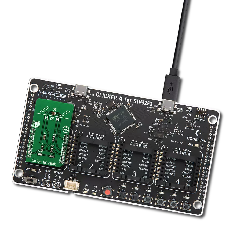
Click board™
Color Click
Dev. board
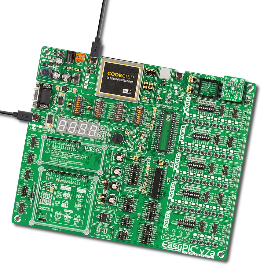
EasyPIC v7a
Compiler
NECTO Studio
MCU
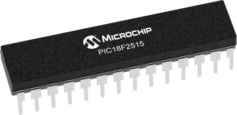
PIC18F2515
Detect various light components such as red, green, blue (RGB), and clear light
A
A
Hardware Overview
How does it work?
Color Click is based on the TCS3471, a color light-to-digital converter from ams AG. The TCS3471 color sensor features a 4x4 array of photo-diodes, which allow the detection of each light component: red, green, and blue (R, G, B). Additionally, it can sense the clear light component, too. The sensor IC has a programmable gain control (for all segments simultaneously), applying gain ratios of 1, 4, 16, and 60. The sensor has an integrating 16-bit ADC section for each channel, performing signal integration, which affects both the sensitivity and the acquisition time. The sensor has no IR filter;
thus, it must be placed under the IR-blocking glass if sensing ambient light. However, it is ideally suited for RGB lighting applications since the LEDs emit light in reasonably narrow spectrum bands with no IR component. In such a scenario, the sensor can achieve a dynamic range of up to 1,000,000:1. Color Click uses a standard 2-wire I2C interface to communicate with the host MCU supporting I2C fast mode with a clock frequency of up to 400kHz. The TCS3471 uses an interrupt INT pin to alert the MCU when a certain condition is reached. The ams AG RGB LED is controlled directly via the GPIO
pins of the host microcontroller, the RD, GR, and BL pins. Instead of HIGH or LOW logic levels, bringing the PWM signal to these pins allows brightness control of the R, G, and B segments of the LRTB GFTG. This Click board™ can operate with either 3.3V or 5V logic voltage levels selected via the PWR SEL jumper. This way, both 3.3V and 5V capable MCUs can use the communication lines properly. Also, this Click board™ comes equipped with a library containing easy-to-use functions and an example code that can be used as a reference for further development.

Features overview
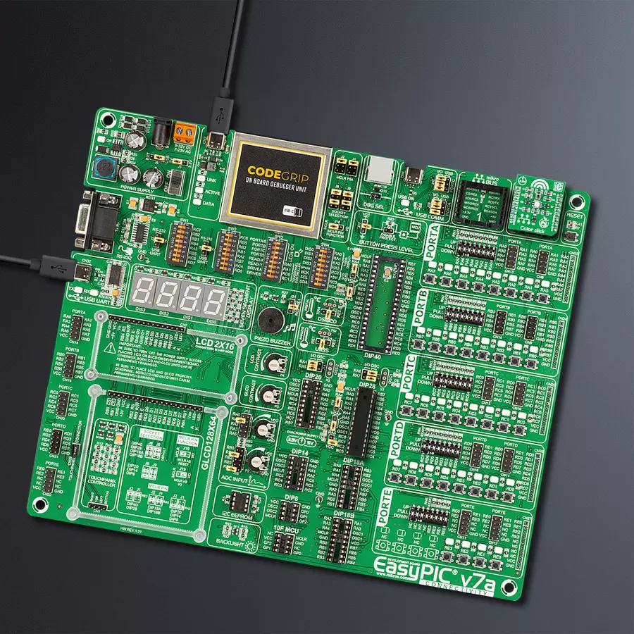
Development board
EasyPIC v7a is the seventh generation of PIC development boards specially designed for the needs of rapid development of embedded applications. It supports a wide range of 8-bit PIC microcontrollers from Microchip and has a broad set of unique functions, such as the first-ever embedded debugger/programmer over USB-C. The development board is well organized and designed so that the end-user has all the necessary elements in one place, such as switches, buttons, indicators, connectors, and others. With four different connectors for each port, EasyPIC v7a allows you to connect accessory boards, sensors, and custom electronics more efficiently than ever. Each part of the EasyPIC v7a development board
contains the components necessary for the most efficient operation of the same board. In addition to the advanced integrated CODEGRIP programmer/debugger module, which offers many valuable programming/debugging options and seamless integration with the Mikroe software environment, the board also includes a clean and regulated power supply module for the development board. It can use various external power sources, including an external 12V power supply, 7-23V AC or 9-32V DC via DC connector/screw terminals, and a power source via the USB Type-C (USB-C) connector. Communication options such as USB-UART and RS-232 are also included, alongside the well-
established mikroBUS™ standard, three display options (7-segment, graphical, and character-based LCD), and several different DIP sockets. These sockets cover a wide range of 8-bit PIC MCUs, from PIC10F, PIC12F, PIC16F, PIC16Enh, PIC18F, PIC18FJ, and PIC18FK families. EasyPIC v7a is an integral part of the Mikroe ecosystem for rapid development. Natively supported by Mikroe software tools, it covers many aspects of prototyping and development thanks to a considerable number of different Click boards™ (over a thousand boards), the number of which is growing every day.

Microcontroller Overview
MCU Card / MCU
Architecture
PIC
MCU Memory (KB)
48
Silicon Vendor
Microchip
Pin count
28
RAM (Bytes)
3968
Used MCU Pins
mikroBUS™ mapper
Take a closer look
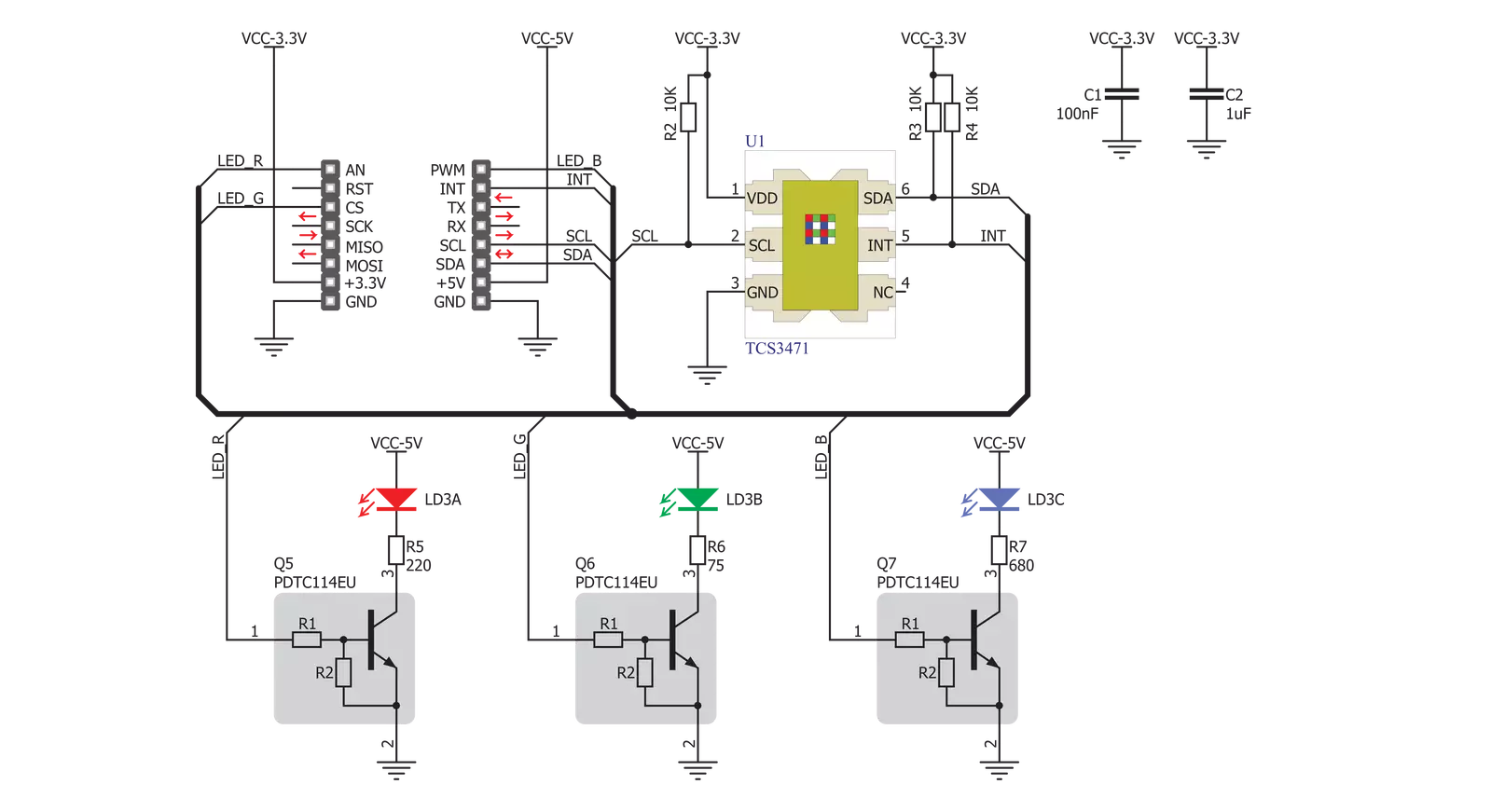
Click board™ Schematic
Step by step
Project assembly

Start by selecting your development board and Click board™. Begin with the EasyPIC v7a as your development board.


Track your results in real time
Application Output
1. Application Output - In Debug mode, the 'Application Output' window enables real-time data monitoring, offering direct insight into execution results. Ensure proper data display by configuring the environment correctly using the provided tutorial.

2. UART Terminal - Use the UART Terminal to monitor data transmission via a USB to UART converter, allowing direct communication between the Click board™ and your development system. Configure the baud rate and other serial settings according to your project's requirements to ensure proper functionality. For step-by-step setup instructions, refer to the provided tutorial.

3. Plot Output - The Plot feature offers a powerful way to visualize real-time sensor data, enabling trend analysis, debugging, and comparison of multiple data points. To set it up correctly, follow the provided tutorial, which includes a step-by-step example of using the Plot feature to display Click board™ readings. To use the Plot feature in your code, use the function: plot(*insert_graph_name*, variable_name);. This is a general format, and it is up to the user to replace 'insert_graph_name' with the actual graph name and 'variable_name' with the parameter to be displayed.

Software Support
Library Description
This library contains API for Color Click driver.
Key functions:
color_read_color_ratio- This function reads desired color ratio from registercolor_get_color_value- This function reads 3 color filters and clear filters and converts the resulting color from RGBC to HSLcolor_get_color- This function determines which color is read by click sensor function has been invoked previously.
Open Source
Code example
The complete application code and a ready-to-use project are available through the NECTO Studio Package Manager for direct installation in the NECTO Studio. The application code can also be found on the MIKROE GitHub account.
/*!
 * \file
 * \brief Color Click example
 *
 * # Description
 * This demo shows color detection/recognition
 * functionality of the Click.
 *
 * The demo application is composed of two sections :
 *
 * ## Application Init
 * Initializes device and driver.
 *
 * ## Application Task
 * Checks which color is detected by the sensor.
 * The name of the detected color is logged on the USBUART.
 *
 *
 * \author MikroE Team
 *
 */
// ------------------------------------------------------------------- INCLUDES

#include "board.h"
#include "log.h"
#include "color.h"

// ------------------------------------------------------------------ VARIABLES

static color_t color;
static log_t logger;

static uint8_t is_color;
static float color_value;

// ------------------------------------------------------ APPLICATION FUNCTIONS

void application_init ( void )
{
    log_cfg_t log_cfg;
    color_cfg_t cfg;

    /**
     * Logger initialization.
     * Default baud rate: 115200
     * Default log level: LOG_LEVEL_DEBUG
     * @note If USB_UART_RX and USB_UART_TX
     * are defined as HAL_PIN_NC, you will
     * need to define them manually for log to work.
     * See @b LOG_MAP_USB_UART macro definition for detailed explanation.
     */
    LOG_MAP_USB_UART( log_cfg );
    log_init( &logger, &log_cfg );
    log_info( &logger, "---- Application Init ----" );

    //  Click initialization.

    color_cfg_setup( &cfg );
    COLOR_MAP_MIKROBUS( cfg, MIKROBUS_1 );
    color_init( &color, &cfg );
    color_default_cfg( &color );
    is_color = 0;
}

void application_task ( void )
{
    color_value = color_get_color_value( &color );
    is_color = color_get_color( color_value );

    switch( is_color )
    {
        case ORANGE_COLOR_FLAG:
        {
            log_printf( &logger, "--- Color: ORANGE\r\n" );
            break;
        }
        case RED_COLOR_FLAG:
        {
            log_printf( &logger, "--- Color: RED\r\n" );
            break;
        }
        case PINK_COLOR_FLAG:
        {
            log_printf( &logger, "--- Color: PINK\r\n" );
            break;
        }
        case PURPLE_COLOR_FLAG:
        {
            log_printf( &logger, "--- Color: PURPLE\r\n" );
            break;
        }
        case BLUE_COLOR_FLAG:
        {
            log_printf( &logger, "--- Color: BLUE\r\n" );
            break;
        }
        case CYAN_COLOR_FLAG:
        {
            log_printf( &logger, "--- Color: CYAN\r\n" );
            break;
        }
        case GREEN_COLOR_FLAG:
        {
            log_printf( &logger, "--- Color: GREEN\r\n" );
            break;
        }
        case YELLOW_COLOR_FLAG:
        {
            log_printf( &logger, "--- Color: YELLOW\r\n" );
            break;
        }
        default:
        {
            break;
        }
    }

    Delay_ms ( 300 );
}

int main ( void )
{
    /* Do not remove this line or clock might not be set correctly. */
    #ifdef PREINIT_SUPPORTED
    preinit();
    #endif

    application_init( );

    for ( ; ; )
    {
        application_task( );
    }

    return 0;
}


// ------------------------------------------------------------------------ END