Create a reliable and innovative current limiting solution with MAX890L and PIC18LF2585
Redefining safety and efficiency: The future of current limiting
Published Dec 29, 2023
Click board™
Current Limit Click
Dev. board
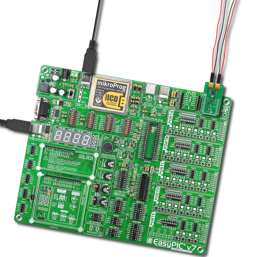
EasyPIC v7
Compiler
NECTO Studio
MCU
PIC18LF2585
Our current limiting solution is engineered to transform control mechanisms, ensuring that current is managed effectively to optimize performance, protect equipment, and enhance safety
A
A
Hardware Overview
How does it work?
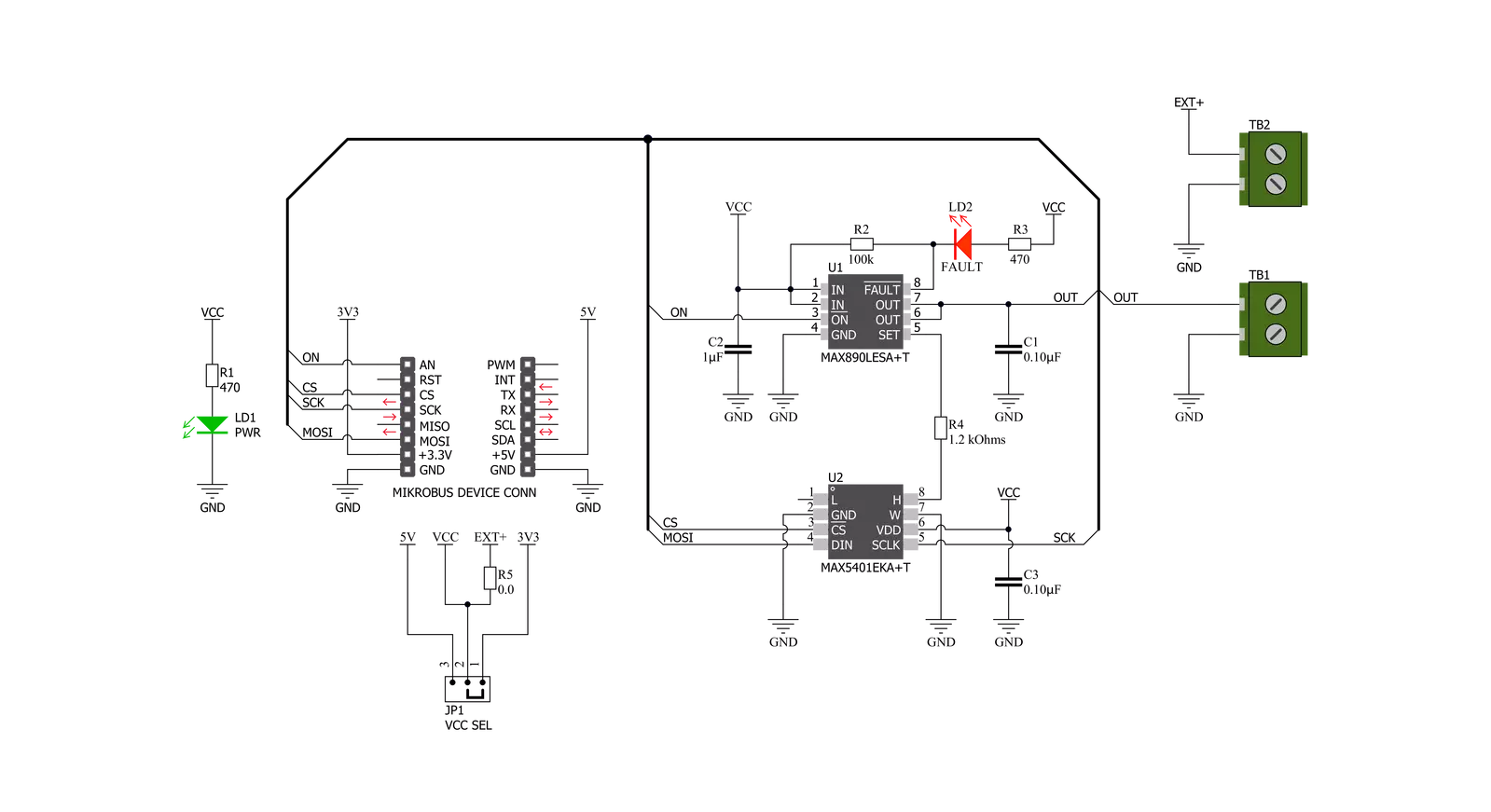
Current Limit Click is based on the MAX890L, a high-side low-resistance P-channel switch with an adjustable, accurate, current limit system and thermal shutdown from Analog Devices. The MAX890L limits the output current to a programmed level. When the output current is increased beyond the programmed current limit (1.2A), the current increases through the internal replica amplifier and the resistance applied to the SET pin. The current-limit error amplifier compares the voltage across the SET pin resistance to the internal +1.24V reference and regulates the current back to the lesser of the programmed limit (1.2A). This switch is not bidirectional, which means the input voltage must be higher than the output voltage. The current-limit switch is virtually
ubiquitous in system control and provides a safe means for regulating the current delivered to a load circuit. It increases the load current to a programmed limit but no higher. Typically, the current limit is a function of the voltage across an external resistor, and this voltage serves as the reference for an internal current-limiting amplifier. Replacing the resistor with a digital potentiometer allows you to program the current limit as performed on this Click board™. For this purpose, the digital potentiometer MAX5401 from Analog Devices that communicates with the MCU via a 3-wire SPI serial interface is used to set the resistance on the SET pin of the MAX890L and thus adjust the current limit for the switch. The MAX890L provides an open-drain fault output
with a red LED, labeled FAULT, to indicate when the current reaches its limit or when the temperature exceeds +135°C. Besides the fault-indicator pin, the MAX890L also has an active-low Switch-On pin labeled ON pin of the mikroBUS™ socket used to enable and turn the switch on. This Click board™ is designed to operate with 3.3V and 5V logic voltage levels that can be selected via the VCC SEL jumper. Additionally, there is a possibility in this selection that as a source of logical voltage level, a voltage from an external input terminal in the range from 2.7 to 5.5V can be used. In this way, using a logic voltage level from mikroBUS™ or an external voltage supply allows both 3.3V and 5V capable MCUs to use the SPI communication lines properly.

Features overview
Development board
EasyPIC v7 is the seventh generation of PIC development boards specially designed to develop embedded applications rapidly. It supports a wide range of 8-bit PIC microcontrollers from Microchip and has a broad set of unique functions, such as a powerful onboard mikroProg programmer and In-Circuit debugger over USB-B. The development board is well organized and designed so that the end-user has all the necessary elements in one place, such as switches, buttons, indicators, connectors, and others. With four different connectors for each port, EasyPIC v7 allows you to connect accessory boards, sensors, and custom electronics more efficiently than ever. Each part of
the EasyPIC v7 development board contains the components necessary for the most efficient operation of the same board. An integrated mikroProg, a fast USB 2.0 programmer with mikroICD hardware In-Circuit Debugger, offers many valuable programming/debugging options and seamless integration with the Mikroe software environment. Besides it also includes a clean and regulated power supply block for the development board. It can use various external power sources, including an external 12V power supply, 7-23V AC or 9-32V DC via DC connector/screw terminals, and a power source via the USB Type-B (USB-B) connector. Communication options such as
USB-UART and RS-232 are also included, alongside the well-established mikroBUS™ standard, three display options (7-segment, graphical, and character-based LCD), and several different DIP sockets. These sockets cover a wide range of 8-bit PIC MCUs, from PIC10F, PIC12F, PIC16F, PIC16Enh, PIC18F, PIC18FJ, and PIC18FK families. EasyPIC v7 is an integral part of the Mikroe ecosystem for rapid development. Natively supported by Mikroe software tools, it covers many aspects of prototyping and development thanks to a considerable number of different Click boards™ (over a thousand boards), the number of which is growing every day.

Microcontroller Overview
MCU Card / MCU
Architecture
PIC
MCU Memory (KB)
48
Silicon Vendor
Microchip
Pin count
28
RAM (Bytes)
3328
Used MCU Pins
mikroBUS™ mapper
Take a closer look
Click board™ Schematic
Step by step
Project assembly

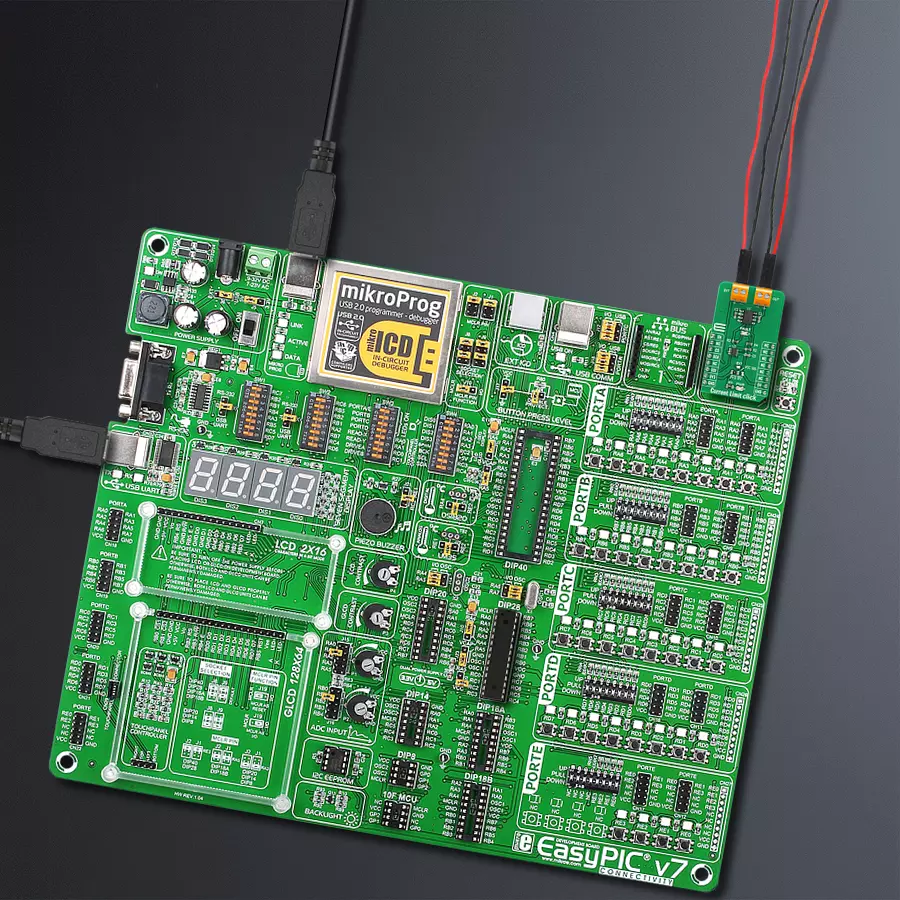
Start by selecting your development board and Click board™. Begin with the EasyPIC v7 as your development board.


Software Support
Library Description
This library contains API for Current Limit Click driver.
Key functions:
currentlimit_dev_enable- Device enable functioncurrentlimit_set_limit- Set Current With Predefined Values Limit functioncurrentlimit_set_limit_calc- Set Calculated Current Limit function
Open Source
Code example
The complete application code and a ready-to-use project are available through the NECTO Studio Package Manager for direct installation in the NECTO Studio. The application code can also be found on the MIKROE GitHub account.
/*!
* @file main.c
* @brief CurrentLimit Click example
*
* # Description
* This example shows capabilities of Current Limit Click board.
*
* The demo application is composed of two sections :
*
* ## Application Init
* Initalizes SPI driver and enables the device.
*
* ## Application Task
* Reading users input from USART terminal and using it as an index for
* an array of pre-calculated values that define current limit level.
*
*
* @author Stefan Ilic
*
*/
#include "board.h"
#include "log.h"
#include "currentlimit.h"
static currentlimit_t currentlimit;
static log_t logger;
const uint8_t lim_val[ 8 ] = { 223, 241, 247, 250, 252, 253, 254, 255 };
uint16_t lim_data[8] = { 100, 200, 300, 400, 500, 600, 700, 867 };
void display_settings ( void ) {
log_printf( &logger, "- - - - - - - - - - - - - - - \r\n" );
log_printf( &logger, " To select current limit \r\n" );
log_printf( &logger, " Send one of the numbers \r\n" );
log_printf( &logger, "- - - - - - - - - - - - - - - \r\n" );
log_printf( &logger, " 1 - Limited to 100 mA \r\n" );
log_printf( &logger, " 2 - Limited to 200 mA \r\n" );
log_printf( &logger, " 3 - Limited to 300 mA \r\n" );
log_printf( &logger, " 4 - Limited to 400 mA \r\n" );
log_printf( &logger, " 5 - Limited to 500 mA \r\n" );
log_printf( &logger, " 6 - Limited to 600 mA \r\n" );
log_printf( &logger, " 7 - Limited to 700 mA \r\n" );
log_printf( &logger, " 8 - Limited to 867 mA \r\n" );
log_printf( &logger, "- - - - - - - - - - - - - - - \r\n" );
}
void application_init ( void ) {
log_cfg_t log_cfg; /**< Logger config object. */
currentlimit_cfg_t currentlimit_cfg; /**< Click config object. */
/**
* Logger initialization.
* Default baud rate: 115200
* Default log level: LOG_LEVEL_DEBUG
* @note If USB_UART_RX and USB_UART_TX
* are defined as HAL_PIN_NC, you will
* need to define them manually for log to work.
* See @b LOG_MAP_USB_UART macro definition for detailed explanation.
*/
LOG_MAP_USB_UART( log_cfg );
log_init( &logger, &log_cfg );
log_info( &logger, " Application Init " );
// Click initialization.
currentlimit_cfg_setup( ¤tlimit_cfg );
CURRENTLIMIT_MAP_MIKROBUS( currentlimit_cfg, MIKROBUS_1 );
err_t init_flag = currentlimit_init( ¤tlimit, ¤tlimit_cfg );
if ( SPI_MASTER_ERROR == init_flag ) {
log_error( &logger, " Application Init Error. " );
log_info( &logger, " Please, run program again... " );
for ( ; ; );
}
currentlimit_dev_enable( ¤tlimit, CURRENTLIMIT_ENABLE );
log_printf( &logger, " Click Enabled! \r\n" );
log_printf( &logger, "-----------------------\r\n" );
Delay_ms ( 100 );
log_info( &logger, " Application Task " );
display_settings( );
}
void application_task ( void ) {
char inx;
if ( log_read( &logger, &inx, 1 ) != CURRENTLIMIT_ERROR ) {
if ( inx >= '1' && inx <= '8' ) {
currentlimit_set_limit( ¤tlimit, lim_val[ inx - 49 ] );
log_printf( &logger, " Selected mode %d, \r\n Current limit is %d mA \r\n", ( uint16_t ) inx - 48, lim_data[ inx - 49 ] );
log_printf( &logger, "- - - - - - - - - - - - - - - \r\n" );
} else {
log_printf( &logger, "- - - - - - - - - - - - - - - \r\n" );
log_printf( &logger, " Data not in range! \r\n" );
log_printf( &logger, "- - - - - - - - - - - - - - - \r\n" );
display_settings( );
}
}
}
int main ( void )
{
/* Do not remove this line or clock might not be set correctly. */
#ifdef PREINIT_SUPPORTED
preinit();
#endif
application_init( );
for ( ; ; )
{
application_task( );
}
return 0;
}
// ------------------------------------------------------------------------ END
Additional Support
Resources
Category:Power Switch


