Revolutionize temperature monitoring with TMP007 and PIC18F2550
Touch-free temperature tracking

Published Nov 01, 2023
Click board™
IrThermo 2 Click
Dev. board
EasyPIC v7
Compiler
NECTO Studio
MCU
PIC18F2550
Experience the power of contactless temperature monitoring for swift, accurate, and reliable results!
A
A
Hardware Overview
How does it work?
IrThermo 2 Click is based on the TMP007, an infrared thermopile sensor with an integrated Math Engine from Texas Instruments. When there is infrared radiation, and the sensor absorbs it, the integrated Math Engine calculates its temperature by comparing it with the temperature of the silicon die. The sensor is factory calibrated, but the user can adjust the calibration coefficients for specific applications. This adjustment could be the correction for the range, field of view, object shape, and environmental factors. Besides the direct
reading of the object temperature, Math Engine features programmable alerts, nonvolatile memory (EEPROM) for storing calibration coefficients, and transient correction. The IrThermo 2 Click uses an industry-standard I2C interface to communicate with the host MCU over the mikroBUS™ socket. One of eight programmable I2C addresses can be set over the ADR1 and ADR0 solder jumpers labeled ADDR SEL and positions 1 and 0. Those jumpers are set to 0 (GND) by default. It also features an active LOW
alert output on pin AL that can be used as an alert function if the TMP007 is working in an interrupt mode. This Click board™ can operate with either 3.3V or 5V logic voltage levels selected via an onboard jumper. This way, both 3.3V and 5V capable MCUs can use the communication lines properly. However, the Click board™ comes equipped with a library containing easy-to-use functions and an example code that can be used, as a reference, for further development.

Features overview
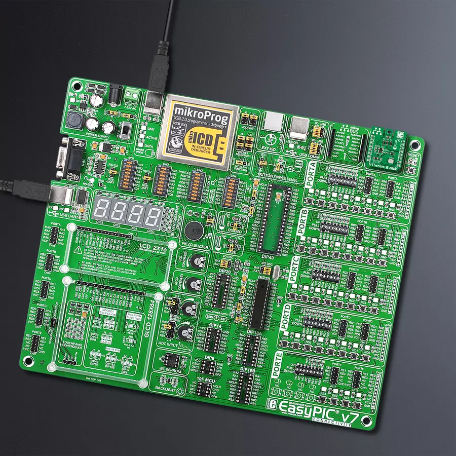
Development board
EasyPIC v7 is the seventh generation of PIC development boards specially designed to develop embedded applications rapidly. It supports a wide range of 8-bit PIC microcontrollers from Microchip and has a broad set of unique functions, such as a powerful onboard mikroProg programmer and In-Circuit debugger over USB-B. The development board is well organized and designed so that the end-user has all the necessary elements in one place, such as switches, buttons, indicators, connectors, and others. With four different connectors for each port, EasyPIC v7 allows you to connect accessory boards, sensors, and custom electronics more efficiently than ever. Each part of
the EasyPIC v7 development board contains the components necessary for the most efficient operation of the same board. An integrated mikroProg, a fast USB 2.0 programmer with mikroICD hardware In-Circuit Debugger, offers many valuable programming/debugging options and seamless integration with the Mikroe software environment. Besides it also includes a clean and regulated power supply block for the development board. It can use various external power sources, including an external 12V power supply, 7-23V AC or 9-32V DC via DC connector/screw terminals, and a power source via the USB Type-B (USB-B) connector. Communication options such as
USB-UART and RS-232 are also included, alongside the well-established mikroBUS™ standard, three display options (7-segment, graphical, and character-based LCD), and several different DIP sockets. These sockets cover a wide range of 8-bit PIC MCUs, from PIC10F, PIC12F, PIC16F, PIC16Enh, PIC18F, PIC18FJ, and PIC18FK families. EasyPIC v7 is an integral part of the Mikroe ecosystem for rapid development. Natively supported by Mikroe software tools, it covers many aspects of prototyping and development thanks to a considerable number of different Click boards™ (over a thousand boards), the number of which is growing every day.

Microcontroller Overview
MCU Card / MCU
Architecture
PIC
MCU Memory (KB)
32
Silicon Vendor
Microchip
Pin count
28
RAM (Bytes)
2048
Used MCU Pins
mikroBUS™ mapper
Take a closer look
Click board™ Schematic

Step by step
Project assembly

Start by selecting your development board and Click board™. Begin with the EasyPIC v7 as your development board.


Software Support
Library Description
This library contains API for IrThermo 2 Click driver.
Key functions:
irthermo2_get_raw_temperature- Function read 16-bit data from raw temperature register and calculate temperature in degrees Celsiusirthermo2_get_object_temperature_c- Function read 16-bit data from object temperature register and calculate temperature in degrees Celsiusirthermo2_get_object_temperature_f- Function read 16-bit data from object temperature register and calculate temperature in degrees Fahrenheit
Open Source
Code example
The complete application code and a ready-to-use project are available through the NECTO Studio Package Manager for direct installation in the NECTO Studio. The application code can also be found on the MIKROE GitHub account.
/*!
 * @file main.c
 * @brief IrThermo2 Click example
 *
 * # Description
 * IrThermo 2 is a non-contact temperature measurement Click. The sensor absorbs the infrared
 * radiation emitted by the target object (withing the sensor’s field of view) and
 * the integrated math engine calculates its temperature by comparing it with the temperature
 * of the silicon die. The measurement range of the sensor is between –40°C to 125°C.
 *
 * The demo application is composed of two sections :
 *
 * ## Application Init
 * Initialization driver enable's - I2C, set default configuration and start write log.
 *
 * ## Application Task
 * This is a example which demonstrates the use of IrThermo 2 Click board.
 * Measures the object temperature value from sensor and calculate temperature in degrees Celsius [ C ].
 * Results are being sent to the USART Terminal where you can track their changes.
 * All data logs on usb uart for aproximetly every 5 sec when the data value changes.
 *
 *
 * @author MikroE Team
 *
 */

#include "board.h"
#include "log.h"
#include "irthermo2.h"


static irthermo2_t irthermo2;
static log_t logger;

static float temperature;


void application_init ( void )
{
    log_cfg_t log_cfg;
    irthermo2_cfg_t cfg;

    /**
     * Logger initialization.
     * Default baud rate: 115200
     * Default log level: LOG_LEVEL_DEBUG
     * @note If USB_UART_RX and USB_UART_TX
     * are defined as HAL_PIN_NC, you will
     * need to define them manually for log to work.
     * See @b LOG_MAP_USB_UART macro definition for detailed explanation.
     */
    LOG_MAP_USB_UART( log_cfg );
    log_init( &logger, &log_cfg );
    log_info( &logger, "---- Application Init ----" );

    //  Click initialization.

    irthermo2_cfg_setup( &cfg );
    IRTHERMO2_MAP_MIKROBUS( cfg, MIKROBUS_1 );
    irthermo2_init( &irthermo2, &cfg );

    irthermo2_default_cfg( &irthermo2 );
    Delay_ms ( 100 );
    log_info( &logger, "---- Application Task ----" );
}

void application_task ( void )
{
    temperature = irthermo2_get_object_temperature_c( &irthermo2 );

    log_printf( &logger, " Temperature : %.2f C\r\n", temperature );
    log_printf( &logger, "---------------------------\r\n" );

    Delay_ms ( 1000 );
}

int main ( void )
{
    /* Do not remove this line or clock might not be set correctly. */
    #ifdef PREINIT_SUPPORTED
    preinit();
    #endif

    application_init( );

    for ( ; ; )
    {
        application_task( );
    }

    return 0;
}

// ------------------------------------------------------------------------ END
Additional Support
Resources
Category:Temperature & humidity


