Unleash efficiency and performance with step-down/step-up regulator based on MIC23099 and PIC18LF27K42
AA/AAA cell buck-boost
Published Nov 01, 2023
Click board™
MIC23099 Click
Dev. board
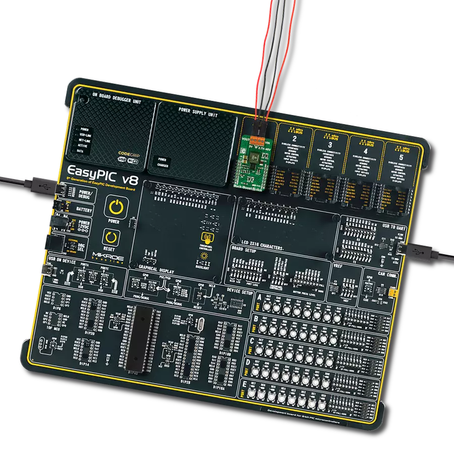
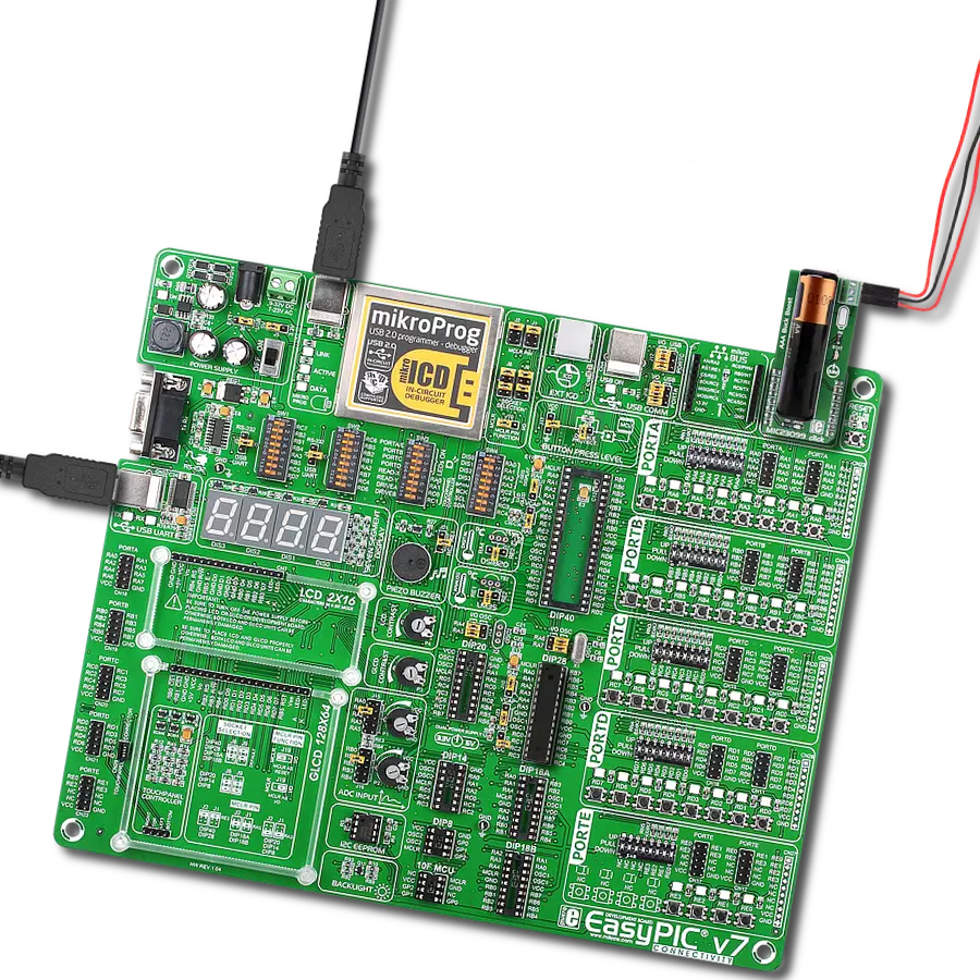
EasyPIC v7
Compiler
NECTO Studio
MCU
PIC18LF27K42
Efficiently manage the power supply for electronic devices that require a voltage different from that provided by a single AA or AAA battery
A
A
Hardware Overview
How does it work?
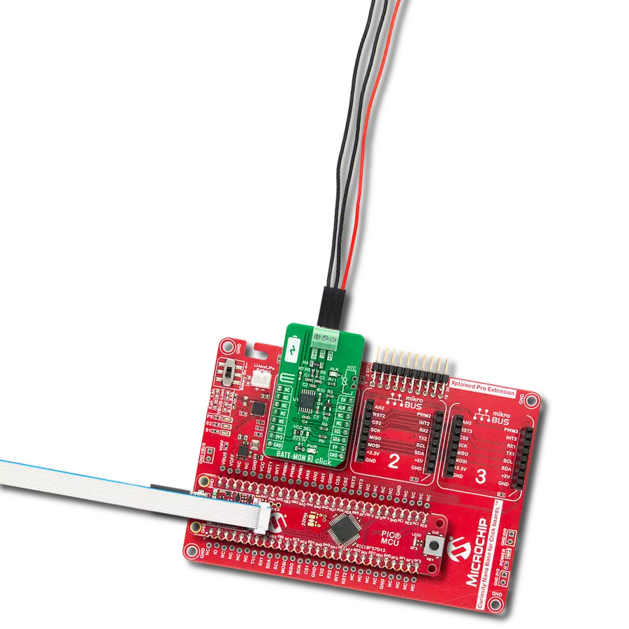
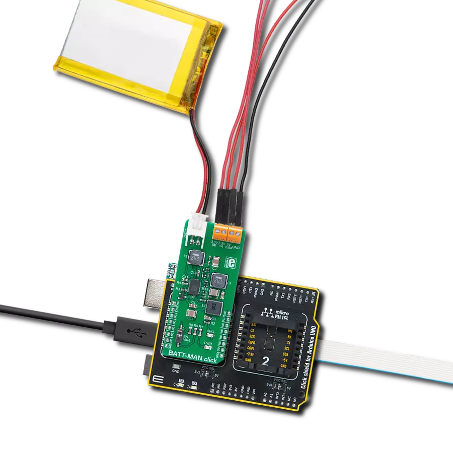
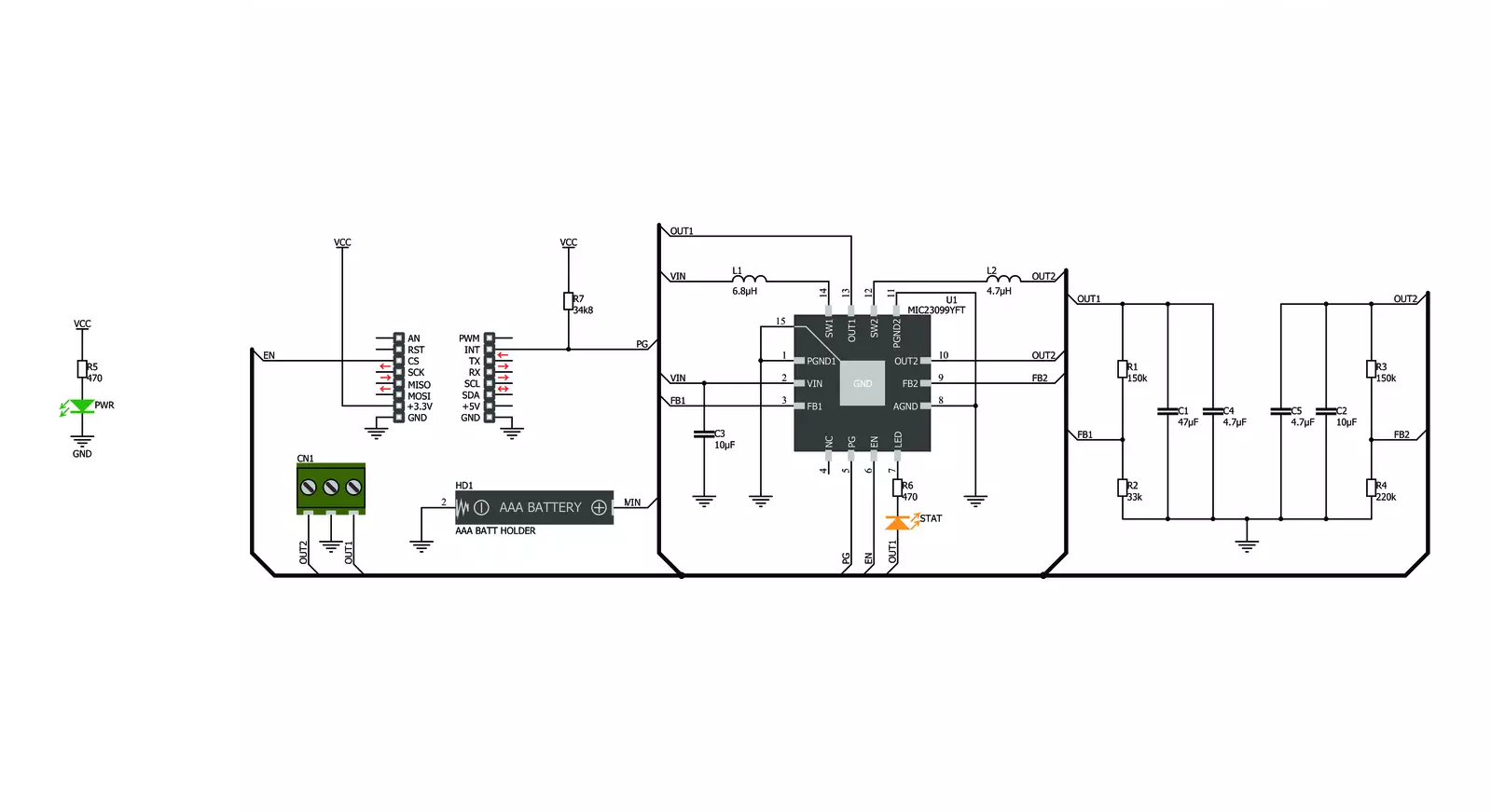
MIC23099 Click is based on the MIC23099, a single AA/AAA cell step-down/step-up regulator with battery monitoring from Microchip. This Click is designed to run on a 3.3V power supply. It communicates with the target microcontroller over the following pins on the mikroBUS™ line: CS, INT. MIC23099 Click has three screw terminals (Buck 1V, GND, and Boost 3V3) which are outputs
for connecting some external consumers. The low-battery level is indicated by an onboard STAT LED. The MIC23099 is not a battery charger but needs a battery to work properly. The battery is not included. The MIC23099 is a high-efficiency, low-noise, dual output, integrated power management solution for single-cell alkaline or NiMH battery applications. Both converters are
designed to operate with a minimum switching frequency of 80 kHz for the buck and 100 kHz for the boost to minimize switching artifacts in the audio band. The high-current boost has a maximum switching frequency of 1 MHz, minimizing the solution footprint. The MIC23099 incorporates both battery management functions and fault protection.


Features overview
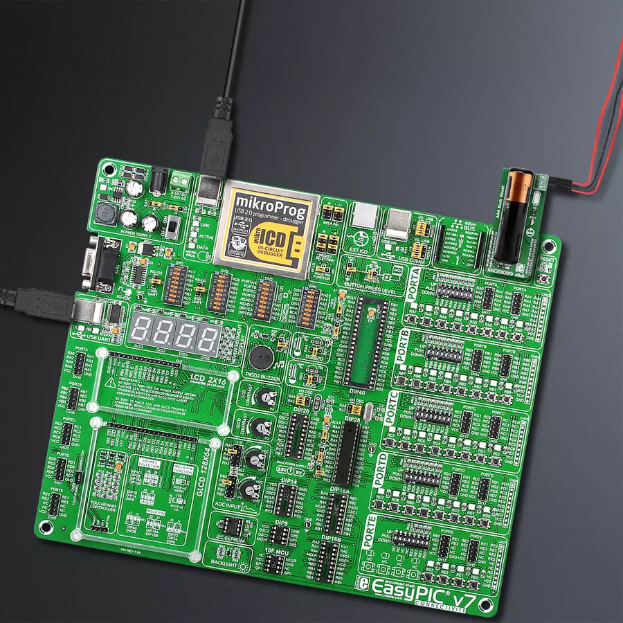
Development board
EasyPIC v7 is the seventh generation of PIC development boards specially designed to develop embedded applications rapidly. It supports a wide range of 8-bit PIC microcontrollers from Microchip and has a broad set of unique functions, such as a powerful onboard mikroProg programmer and In-Circuit debugger over USB-B. The development board is well organized and designed so that the end-user has all the necessary elements in one place, such as switches, buttons, indicators, connectors, and others. With four different connectors for each port, EasyPIC v7 allows you to connect accessory boards, sensors, and custom electronics more efficiently than ever. Each part of
the EasyPIC v7 development board contains the components necessary for the most efficient operation of the same board. An integrated mikroProg, a fast USB 2.0 programmer with mikroICD hardware In-Circuit Debugger, offers many valuable programming/debugging options and seamless integration with the Mikroe software environment. Besides it also includes a clean and regulated power supply block for the development board. It can use various external power sources, including an external 12V power supply, 7-23V AC or 9-32V DC via DC connector/screw terminals, and a power source via the USB Type-B (USB-B) connector. Communication options such as
USB-UART and RS-232 are also included, alongside the well-established mikroBUS™ standard, three display options (7-segment, graphical, and character-based LCD), and several different DIP sockets. These sockets cover a wide range of 8-bit PIC MCUs, from PIC10F, PIC12F, PIC16F, PIC16Enh, PIC18F, PIC18FJ, and PIC18FK families. EasyPIC v7 is an integral part of the Mikroe ecosystem for rapid development. Natively supported by Mikroe software tools, it covers many aspects of prototyping and development thanks to a considerable number of different Click boards™ (over a thousand boards), the number of which is growing every day.

Microcontroller Overview
MCU Card / MCU
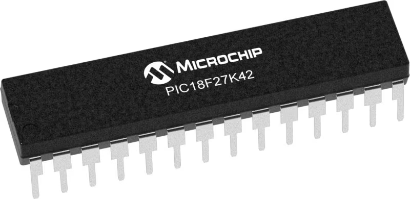
Architecture
PIC
MCU Memory (KB)
128
Silicon Vendor
Microchip
Pin count
28
RAM (Bytes)
8192
Used MCU Pins
mikroBUS™ mapper
Take a closer look
Click board™ Schematic
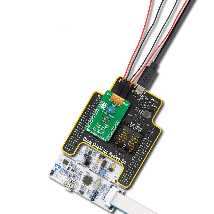
Step by step
Project assembly

Start by selecting your development board and Click board™. Begin with the EasyPIC v7 as your development board.


Track your results in real time
Application Output
1. Application Output - In Debug mode, the 'Application Output' window enables real-time data monitoring, offering direct insight into execution results. Ensure proper data display by configuring the environment correctly using the provided tutorial.

2. UART Terminal - Use the UART Terminal to monitor data transmission via a USB to UART converter, allowing direct communication between the Click board™ and your development system. Configure the baud rate and other serial settings according to your project's requirements to ensure proper functionality. For step-by-step setup instructions, refer to the provided tutorial.

3. Plot Output - The Plot feature offers a powerful way to visualize real-time sensor data, enabling trend analysis, debugging, and comparison of multiple data points. To set it up correctly, follow the provided tutorial, which includes a step-by-step example of using the Plot feature to display Click board™ readings. To use the Plot feature in your code, use the function: plot(*insert_graph_name*, variable_name);. This is a general format, and it is up to the user to replace 'insert_graph_name' with the actual graph name and 'variable_name' with the parameter to be displayed.

Software Support
Library Description
This library contains API for MIC23099 Click driver.
Key functions:
mic23099_default_cfg- This function executes default configuration for MIC23099 Clickmic23099_check_power_good- This function checks the state of Power Good output pin
Open Source
Code example
The complete application code and a ready-to-use project are available through the NECTO Studio Package Manager for direct installation in the NECTO Studio. The application code can also be found on the MIKROE GitHub account.
/*!
 * \file
 * \brief MIC23099 Click example
 *
 * # Description
 * MIC23099 Click represent single AA/AAA cell step-down/step-up regulator
 * with battery monitoring.
 *
 * The demo application is composed of two sections :
 *
 * ## Application Init
 * Application Init performs Logger and Click initialization.
 *
 * ## Application Task
 * This example demonstrates the use of MIC23099 Click board by checking
 * the state of power good pin and sends note via UART Terminal
 * if the state is low.
 *
 * \author Mihajlo Djordjevic
 *
 */
// ------------------------------------------------------------------- INCLUDES

#include "board.h"
#include "log.h"
#include "mic23099.h"

// ------------------------------------------------------------------ VARIABLES

static mic23099_t mic23099;
static log_t logger;

static uint8_t new_stat;
static uint8_t old_stat;

// ------------------------------------------------------- ADDITIONAL FUNCTIONS


// ------------------------------------------------------ APPLICATION FUNCTIONS

void application_init ( void )
{
    log_cfg_t log_cfg;
    mic23099_cfg_t cfg;

    /**
     * Logger initialization.
     * Default baud rate: 115200
     * Default log level: LOG_LEVEL_DEBUG
     * @note If USB_UART_RX and USB_UART_TX
     * are defined as HAL_PIN_NC, you will
     * need to define them manually for log to work.
     * See @b LOG_MAP_USB_UART macro definition for detailed explanation.
     */
    LOG_MAP_USB_UART( log_cfg );
    log_init( &logger, &log_cfg );
    log_printf( &logger, "--------------------------\r\n" );
    log_printf( &logger, "     Application  Init\r\n" );
    Delay_ms ( 1000 );

    //  Click initialization.

    mic23099_cfg_setup( &cfg );
    MIC23099_MAP_MIKROBUS( cfg, MIKROBUS_1 );
    mic23099_init( &mic23099, &cfg );

    log_printf( &logger, "--------------------------\r\n" );
    log_printf( &logger, " ---- MIC23099 Click ---- \r\n" );
    log_printf( &logger, "--------------------------\r\n" );
    Delay_ms ( 1000 );

    mic23099_default_cfg( &mic23099 );
    Delay_ms ( 1000 );

    new_stat = MIC23099_DISABLE;
    old_stat = MIC23099_ENABLE;

    log_printf( &logger, " -- Initialization done --\r\n" );
    log_printf( &logger, "--------------------------\r\n" );
    Delay_ms ( 1000 );
}

void application_task ( void )
{
    new_stat = mic23099_check_power_good( &mic23099 );

    if ( new_stat == MIC23099_ENABLE && old_stat == MIC23099_DISABLE )
    {
        old_stat = MIC23099_ENABLE;
    }

    if ( new_stat == MIC23099_DISABLE && old_stat == MIC23099_ENABLE )
    {
        log_printf( &logger, " Change  battery  and  reset. \r\n" );
        log_printf( &logger, "------------------------------\r\n" );
        old_stat = MIC23099_DISABLE;
    }
}

int main ( void )
{
    /* Do not remove this line or clock might not be set correctly. */
    #ifdef PREINIT_SUPPORTED
    preinit();
    #endif

    application_init( );

    for ( ; ; )
    {
        application_task( );
    }

    return 0;
}

// ------------------------------------------------------------------------ END