Achieve ultimate control and comfort with BPS230 and PIC18LF2515
Keep humidity and temperature in check for ultimate balance

Published Nov 01, 2023
Click board™
Temp&Hum 10 Click
Dev. board
EasyPIC v7
Compiler
NECTO Studio
MCU
PIC18LF2515
From homes to industrial facilities, our solutions adapt to diverse settings, providing crucial data for maintaining optimal conditions in any space.
A
A
Hardware Overview
How does it work?
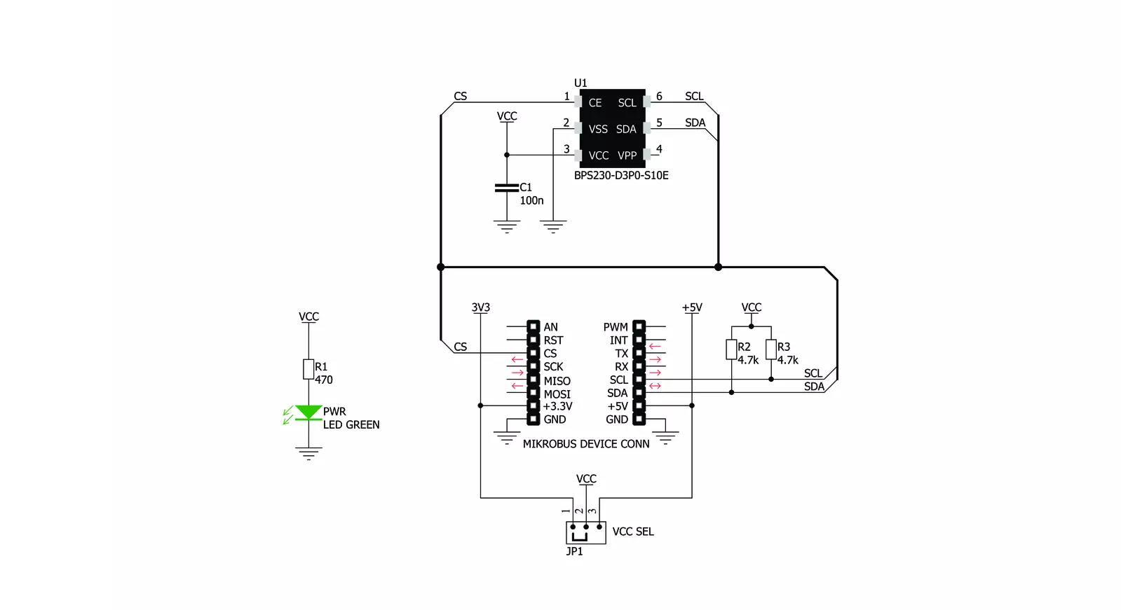
Temp&Hum 10 Click is based on the BPS230, a relative humidity and temperature sensor with I2C interface from Bourns. This sensor IC integrates two very accurate sensing components: temperature sensor, and relative humidity sensor. By utilizing the proprietary manufacturing technology, this sensor integrates the complete temperature and humidity measurement system on chip. The output data is processed and compensated by the BPS230 sensor IC itself, requiring only basic conversion formulas to be applied within the firmware of the host microcontroller (MCU). These conversion formulas are given in the BPS230 datasheet and provide readings in °C and %RH, directly. The BPS230 incorporates an accurate bandgap temperature sensor, which can measure the temperature in the range between -30 °C and 100 °C while retaining accuracy of ±0.4°C, typically. The accuracy is even greater if the range is narrowed down: when used over the range between -10°C and 70°C, the typical accuracy is ±0.1 °C. Also, the reproducibility of the temperature measurement is very good, in the range of 0.1°C. The BPS230 sensor IC can be reliably used for prolonged periods of time.
After the measurement has been converted by a high-precision ADC, it is fed to a logic back-end which applies
factory-calibrated correction and converts the raw data into a compensated value. By applying a simple conversion formula, the measurement can be easily converted in °C. The raw temperature measurement value is in the 11-bit format. Please note that the sensor will take some time to accommodate to the ambient temperature, especially if the temperature changes quickly, considering the thermal conductivity of the PCB itself. The response time of both sensors is also affected by the averaging ratio, which can be configured over the I2C interface. The humidity sensor is a capacitor type polymer-based sensor which changes the capacitance proportionally to the relative humidity. However, the capacitance of this sensor is affected by changes of the ambient temperature, as well. The accuracy of the RH sensor varies in the range between ±3% and ±5%, depending on the measurement conditions (ambient temperature). After the measurement has been converted by a high-precision ADC, it is fed to the logic back-end which applies factory-calibrated correction and converts the raw data into a compensated value. By applying a simple conversion formula, the measurement can be easily converted in %RH. The raw RH measurement value is in the 10-bit format. Please note
that capacitor-based humidity sensors commonly suffer from a small hysteresis, which may occur if the sensor is used in very humid conditions for prolonged periods of time. However, this hysteresis is not irreversible. The BPS230 datasheet specifies that its hysteresis should stay within the range of ±1 %RH. The CS pin of the mikroBUS™ is routed to the CE pin of the BPS230 sensor IC. This pin is used to set the operating mode of the sensor by the host MCU either in Sleep or StandBy mode. When there is a LOW logic level on the CS pin, the device operates in Sleep mode. While in Sleep mode, the power consumption is reduced to a minimum: the internal clock of the IC is stopped, and the I2C interface is disabled. By applying a HIGH logic level to this pin, the IC enters the StandBy mode, with the I2C interface enabled. Temp&Hum 10 click uses the I2C communication interface. It has pull-up resistors connected to a selectable voltage source. A small SMD jumper can be used to switch between 3.3V and 5V. This jumper switches the voltage for both the IC and two pull-up resistors, allowing the Click board™ to be used with a wide range of MCUs, both using 3.3V and 5V.

Features overview
Development board
EasyPIC v7 is the seventh generation of PIC development boards specially designed to develop embedded applications rapidly. It supports a wide range of 8-bit PIC microcontrollers from Microchip and has a broad set of unique functions, such as a powerful onboard mikroProg programmer and In-Circuit debugger over USB-B. The development board is well organized and designed so that the end-user has all the necessary elements in one place, such as switches, buttons, indicators, connectors, and others. With four different connectors for each port, EasyPIC v7 allows you to connect accessory boards, sensors, and custom electronics more efficiently than ever. Each part of
the EasyPIC v7 development board contains the components necessary for the most efficient operation of the same board. An integrated mikroProg, a fast USB 2.0 programmer with mikroICD hardware In-Circuit Debugger, offers many valuable programming/debugging options and seamless integration with the Mikroe software environment. Besides it also includes a clean and regulated power supply block for the development board. It can use various external power sources, including an external 12V power supply, 7-23V AC or 9-32V DC via DC connector/screw terminals, and a power source via the USB Type-B (USB-B) connector. Communication options such as
USB-UART and RS-232 are also included, alongside the well-established mikroBUS™ standard, three display options (7-segment, graphical, and character-based LCD), and several different DIP sockets. These sockets cover a wide range of 8-bit PIC MCUs, from PIC10F, PIC12F, PIC16F, PIC16Enh, PIC18F, PIC18FJ, and PIC18FK families. EasyPIC v7 is an integral part of the Mikroe ecosystem for rapid development. Natively supported by Mikroe software tools, it covers many aspects of prototyping and development thanks to a considerable number of different Click boards™ (over a thousand boards), the number of which is growing every day.

Microcontroller Overview
MCU Card / MCU
Architecture
PIC
MCU Memory (KB)
48
Silicon Vendor
Microchip
Pin count
28
RAM (Bytes)
3968
Used MCU Pins
mikroBUS™ mapper
Take a closer look
Click board™ Schematic
Step by step
Project assembly

Start by selecting your development board and Click board™. Begin with the EasyPIC v7 as your development board.


Track your results in real time
Application Output
1. Application Output - In Debug mode, the 'Application Output' window enables real-time data monitoring, offering direct insight into execution results. Ensure proper data display by configuring the environment correctly using the provided tutorial.

2. UART Terminal - Use the UART Terminal to monitor data transmission via a USB to UART converter, allowing direct communication between the Click board™ and your development system. Configure the baud rate and other serial settings according to your project's requirements to ensure proper functionality. For step-by-step setup instructions, refer to the provided tutorial.

3. Plot Output - The Plot feature offers a powerful way to visualize real-time sensor data, enabling trend analysis, debugging, and comparison of multiple data points. To set it up correctly, follow the provided tutorial, which includes a step-by-step example of using the Plot feature to display Click board™ readings. To use the Plot feature in your code, use the function: plot(*insert_graph_name*, variable_name);. This is a general format, and it is up to the user to replace 'insert_graph_name' with the actual graph name and 'variable_name' with the parameter to be displayed.

Software Support
Library Description
This library contains API for Temp&Hum 10 Click driver.
Key functions:
temphum10_get_temperature- Functions for read Temperature datatemphum10_set_device_mode- Functions for sets Device modetemphum10_repeat_measurement- Functions for repeat measurement
Open Source
Code example
The complete application code and a ready-to-use project are available through the NECTO Studio Package Manager for direct installation in the NECTO Studio. The application code can also be found on the MIKROE GitHub account.
/*!
 * \file
 * \brief TempHum10 Click example
 *
 * # Description
 * This application measures temperature and humidity.
 *
 * The demo application is composed of two sections :
 *
 * ## Application Init
 * Initialization driver init and sets device mode
 *
 * ## Application Task
 * Reads Temperature and Humidity data and logs this data to USBUART every 1 sec.
 *
 *  ## NOTE
 * If you are expiriencing issues with comunication, please try another mikroBUS socket or set the VCC SEL jumper at 5V.
 *
 * \author MikroE Team
 *
 */
// ------------------------------------------------------------------- INCLUDES

#include "board.h"
#include "log.h"
#include "temphum10.h"

// ------------------------------------------------------------------ VARIABLES

static temphum10_t temphum10;
static log_t logger;

// ------------------------------------------------------ APPLICATION FUNCTIONS

void application_init ( void )
{
    log_cfg_t log_cfg;
    temphum10_cfg_t cfg;
    uint8_t tmp;

    /**
     * Logger initialization.
     * Default baud rate: 115200
     * Default log level: LOG_LEVEL_DEBUG
     * @note If USB_UART_RX and USB_UART_TX
     * are defined as HAL_PIN_NC, you will
     * need to define them manually for log to work.
     * See @b LOG_MAP_USB_UART macro definition for detailed explanation.
     */
    LOG_MAP_USB_UART( log_cfg );
    log_init( &logger, &log_cfg );
    log_info( &logger, "---- Application Init ----" );

    //  Click initialization.

    temphum10_cfg_setup( &cfg );
    TEMPHUM10_MAP_MIKROBUS( cfg, MIKROBUS_1 );
    temphum10_init( &temphum10, &cfg );

    log_info( &logger, "---- Device config ----" );

    temphum10_set_device_mode( &temphum10, TEMPHUM10_MODE_STANDBY );
    Delay_ms ( 100 );

    tmp = TEMPHUM10_RST_NORMAL_OPERATION;
    temphum10_generic_write( &temphum10, TEMPHUM10_REG_DEVICE_RESET, &tmp, 1 );
    Delay_ms ( 100 );
    log_info( &logger, "---- Device calibration ----" );
    tmp = TEMPHUM10_AM_TIMES_AVERAGE_MODE_8 | TEMPHUM10_AM_TEMP_AVERAGE_MODE_TIMES_16;
    temphum10_repeat_measurement( &temphum10, tmp );
    temphum10_get_temperature( &temphum10 );
    temphum10_get_humidity( &temphum10 );
    Delay_ms ( 100 );
    temphum10_repeat_measurement( &temphum10, tmp );
    temphum10_get_temperature( &temphum10 );
    temphum10_get_humidity( &temphum10 );
    log_info( &logger, "---- Application Task ----" );
}

void application_task ( )
{
    float temperature = 0;
    float humidity = 0;
    uint8_t tmp;

    tmp = TEMPHUM10_AM_TIMES_AVERAGE_MODE_8 | TEMPHUM10_AM_TEMP_AVERAGE_MODE_TIMES_16;
    temphum10_repeat_measurement( &temphum10, tmp );
    temperature = temphum10_get_temperature( &temphum10 );
    humidity = temphum10_get_humidity( &temphum10 );

    log_printf( &logger, " Temperature : %.2f \r\n", temperature );
    log_printf( &logger, " Humidity :  %.2f \r\n", humidity );
    log_printf( &logger, "---------------------\r\n" );

    Delay_ms ( 1000 );
}

int main ( void )
{
    /* Do not remove this line or clock might not be set correctly. */
    #ifdef PREINIT_SUPPORTED
    preinit();
    #endif

    application_init( );

    for ( ; ; )
    {
        application_task( );
    }

    return 0;
}

// ------------------------------------------------------------------------ END
Additional Support
Resources
Category:Temperature & humidity


