Manage multiple functions with our 2x2 keyboard based on 74HC32 and STM32F407VGT6
Master your controls: 4 buttons, 1 solution

Published Dec 29, 2023
Click board™
2x2 Key Click
Dev. board
Clicker 4 for STM32F4
Compiler
NECTO Studio
MCU
STM32F407VGT6
Our purpose is to maximize functionality while minimizing complexity with our 4-in-1 button integration
A
A
Hardware Overview
How does it work?
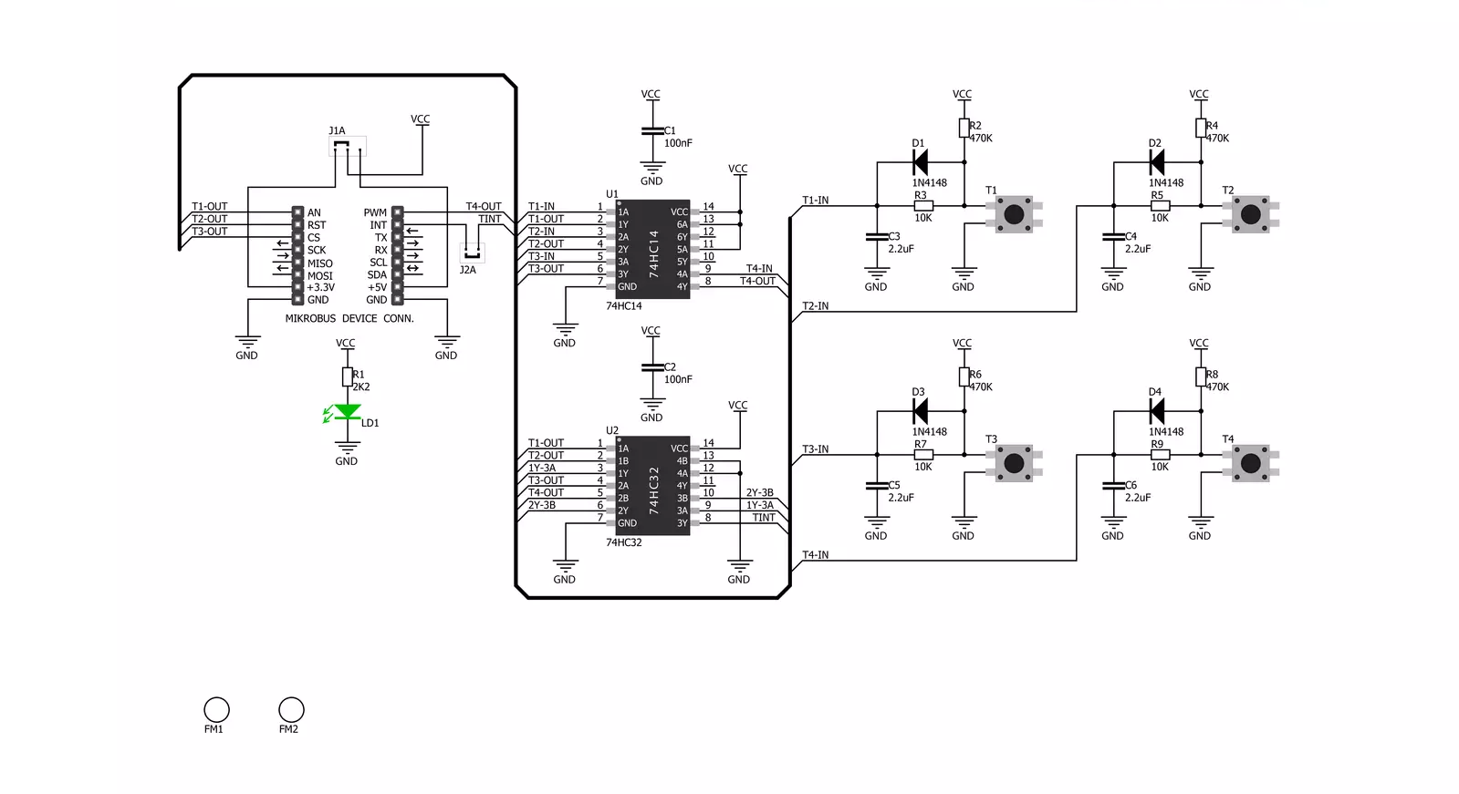
2x2 Key Click is based on the 2x2 button keyboard with debounce circuit, composed of the 74HC32, a quad 2-input OR gate from Nexperia, and the SN74HC14, a Hex Schmitt-Trigger inverter from Texas Instruments. In electronics, two metal components bounce or create multiple signals when they are in contact with each other — like when you push a button — before they reach a stable state. You want a single contact to be recorded, but the microcontroller records this as if you pressed the button many times. So debouncing is, as the name states, the removal of bounces or spikes of low and high voltages.
Graphically speaking, you want a clean line, not spikes. A debounce circuit makes sure that there are no voltage changes on the output. Thanks to it, one button press is recorded as such. All four Schmitt-trigger outputs are connected to the logic OR gate 74HC32 input pins, whose output is directly connected to the INT pin on mikroBUS. This pin is used to signalize an interrupt to the MCU any time a button is pressed. This way, the MCU software can be implemented as a simple polling routine without any delays programmed in the code (like it would be necessary if there weren’t a hardware debouncing circuit present).
Thanks to the INT pin, you can easily program a common interrupt service routine to detect when a button is pressed (the state of the button changes from low to high logic level). This Click board™ can operate with either 3.3V or 5V logic voltage levels selected via the PWR SEL jumper. This way, both 3.3V and 5V capable MCUs can use the communication lines properly. Also, this Click board™ comes equipped with a library containing easy-to-use functions and an example code that can be used as a reference for further development.


Features overview
Development board
Clicker 4 for STM32F4 is a compact development board designed as a complete solution that you can use to quickly build your own gadgets with unique functionalities. Featuring an STM32F407VGT6 MCU, four mikroBUS™ sockets for Click boards™ connectivity, power management, and more, it represents a perfect solution for the rapid development of many different types of applications. At its core is an STM32F407VGT6 MCU, a powerful microcontroller by STMicroelectronics based on the high-performance
Arm® Cortex®-M4 32-bit processor core operating at up to 168 MHz frequency. It provides sufficient processing power for the most demanding tasks, allowing Clicker 4 to adapt to any specific application requirements. Besides two 1x20 pin headers, four improved mikroBUS™ sockets represent the most distinctive connectivity feature, allowing access to a huge base of Click boards™, growing on a daily basis. Each section of Clicker 4 is clearly marked, offering an intuitive and clean interface. This makes working with the
development board much simpler and, thus, faster. The usability of Clicker 4 doesn’t end with its ability to accelerate the prototyping and application development stages: it is designed as a complete solution that can be implemented directly into any project, with no additional hardware modifications required. Four mounting holes [4.2mm/0.165”] at all four corners allow simple installation by using mounting screws.

Microcontroller Overview
MCU Card / MCU

Architecture
ARM Cortex-M4
MCU Memory (KB)
10
Silicon Vendor
STMicroelectronics
Pin count
100
RAM (Bytes)
100
Used MCU Pins
mikroBUS™ mapper
Take a closer look
Click board™ Schematic
Step by step
Project assembly

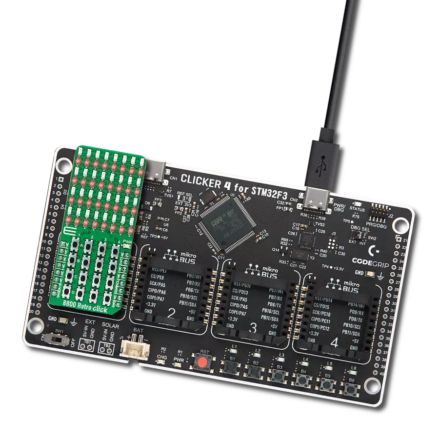
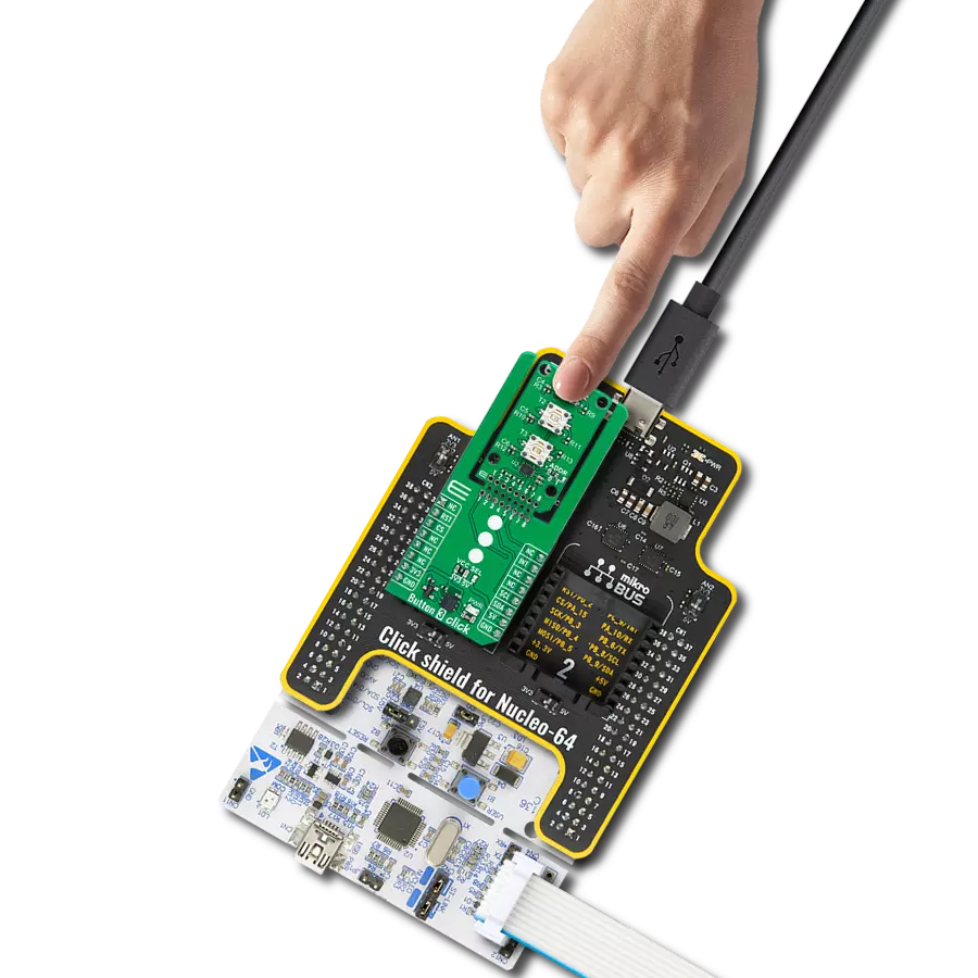
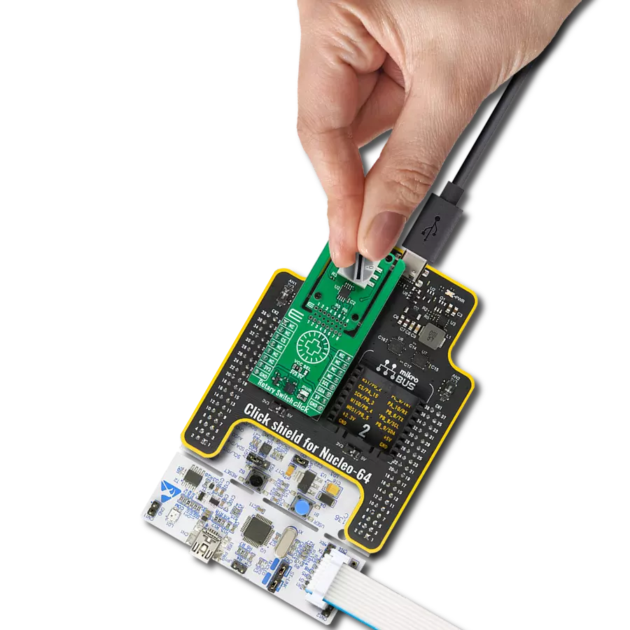
Start by selecting your development board and Click board™. Begin with the Clicker 4 for STM32F4 as your development board.


Track your results in real time
Application Output
1. Application Output - In Debug mode, the 'Application Output' window enables real-time data monitoring, offering direct insight into execution results. Ensure proper data display by configuring the environment correctly using the provided tutorial.

2. UART Terminal - Use the UART Terminal to monitor data transmission via a USB to UART converter, allowing direct communication between the Click board™ and your development system. Configure the baud rate and other serial settings according to your project's requirements to ensure proper functionality. For step-by-step setup instructions, refer to the provided tutorial.

3. Plot Output - The Plot feature offers a powerful way to visualize real-time sensor data, enabling trend analysis, debugging, and comparison of multiple data points. To set it up correctly, follow the provided tutorial, which includes a step-by-step example of using the Plot feature to display Click board™ readings. To use the Plot feature in your code, use the function: plot(*insert_graph_name*, variable_name);. This is a general format, and it is up to the user to replace 'insert_graph_name' with the actual graph name and 'variable_name' with the parameter to be displayed.

Software Support
Library Description
This library contains API for 2x2 Key Click driver.
Key functions:
c2x2key_t1_state- This function gets state of AN pinc2x2key_t2_state- This function gets state of RST pinc2x2key_t3_state- This function gets state of CS pinc2x2key_t4_state- This function gets state of PWM pin
Open Source
Code example
The complete application code and a ready-to-use project are available through the NECTO Studio Package Manager for direct installation in the NECTO Studio. The application code can also be found on the MIKROE GitHub account.
/*!
 * \file
 * \brief 2x2 key Click example
 *
 * # Description
 * 2x2 Key Click has a 4 button keypad and allows multiple key presses.
 *
 * The demo application is composed of two sections :
 *
 * ## Application Init
 * Application Init performs Logger and Click initialization.
 *
 * ## Application Task
 * This example code demonstrates the usage of 2X2 Key Click board.
 * Detects whether any of the keys is pressed where results are being sent
 * to the UART terminal where you can track changes.
 *
 * \author Mihajlo Djordjevic
 *
 */
// ------------------------------------------------------------------- INCLUDES

#include "board.h"
#include "log.h"
#include "c2x2key.h"

uint8_t t1_state     = 0;
uint8_t t1_state_old = 1;
uint8_t t2_state     = 0;
uint8_t t2_state_old = 1;
uint8_t t3_state     = 0;
uint8_t t3_state_old = 1;
uint8_t t4_state     = 0;
uint8_t t4_state_old = 1;

// ------------------------------------------------------------------ VARIABLES

static c2x2key_t c2x2key;
static log_t logger;

// ------------------------------------------------------- ADDITIONAL FUNCTIONS


// ------------------------------------------------------ APPLICATION FUNCTIONS

void application_init ( void )
{
    log_cfg_t log_cfg;
    c2x2key_cfg_t cfg;

    /**
     * Logger initialization.
     * Default baud rate: 115200
     * Default log level: LOG_LEVEL_DEBUG
     * @note If USB_UART_RX and USB_UART_TX
     * are defined as HAL_PIN_NC, you will
     * need to define them manually for log to work.
     * See @b LOG_MAP_USB_UART macro definition for detailed explanation.
     */
    LOG_MAP_USB_UART( log_cfg );
    log_init( &logger, &log_cfg );
    log_printf( &logger, "-- Application  Init --\r\n" );
    Delay_ms ( 1000 );

    //  Click initialization.

    c2x2key_cfg_setup( &cfg );
    C2X2KEY_MAP_MIKROBUS( cfg, MIKROBUS_1 );
    c2x2key_init( &c2x2key, &cfg );

    log_printf( &logger, "-----------------------\r\n" );
    log_printf( &logger, "     2X2 key Click     \r\n" );
    log_printf( &logger, "-----------------------\r\n" );
    Delay_ms ( 1000 );

    log_printf( &logger, "    System is ready    \r\n" );
    log_printf( &logger, "-----------------------\r\n" );
    Delay_ms ( 1000 );
}

void application_task ( void )
{
   t1_state = c2x2key_t1_state( &c2x2key );

   if ( ( t1_state == 1 ) && ( t1_state_old == 0 ) )
    {
        log_printf( &logger, "-----------------------\r\n" );
        log_printf( &logger, "     Key 1 pressed     \r\n" );
        log_printf( &logger, "-----------------------\r\n" );
        t1_state_old = 1;
    }

    if ( ( t1_state == 0 ) && ( t1_state_old == 1 ) )
    {
        t1_state_old = 0;
    }

    t2_state = c2x2key_t2_state( &c2x2key );

   if ( ( t2_state == 1 ) && ( t2_state_old == 0 ) )
    {
        log_printf( &logger, "-----------------------\r\n" );
        log_printf( &logger, "     Key 2 pressed     \r\n" );
        log_printf( &logger, "-----------------------\r\n" );
        t2_state_old = 1;
    }

    if ( ( t2_state == 0 ) && ( t2_state_old == 1 ) )
    {
        t2_state_old = 0;
    }

    t3_state = c2x2key_t3_state( &c2x2key );

   if ( ( t3_state == 1 ) && ( t3_state_old == 0 ) )
    {
        log_printf( &logger, "-----------------------\r\n" );
        log_printf( &logger, "     Key 3 pressed     \r\n" );
        log_printf( &logger, "-----------------------\r\n" );
        t3_state_old = 1;
    }

    if ( ( t3_state == 0 ) && ( t3_state_old == 1 ) )
    {
        t3_state_old = 0;
    }

    t4_state = c2x2key_t4_state( &c2x2key );

   if ( ( t4_state == 1 ) && ( t4_state_old == 0 ) )
    {
        log_printf( &logger, "-----------------------\r\n" );
        log_printf( &logger, "     Key 4 pressed     \r\n" );
        log_printf( &logger, "-----------------------\r\n" );
        t4_state_old = 1;
    }

    if ( ( t4_state == 0 ) && ( t4_state_old == 1 ) )
    {
        t4_state_old = 0;
    }
}

int main ( void )
{
    /* Do not remove this line or clock might not be set correctly. */
    #ifdef PREINIT_SUPPORTED
    preinit();
    #endif

    application_init( );

    for ( ; ; )
    {
        application_task( );
    }

    return 0;
}

// ------------------------------------------------------------------------ END
Additional Support
Resources
Category:Pushbutton/Switches