Experience a new level of environmental monitoring with ICP-10125 and STM32F407VGT6
Your gateway to atmospheric intelligence!

Published Dec 29, 2023
Click board™
Barometer 12 Click
Dev. board
Clicker 4 for STM32F4
Compiler
NECTO Studio
MCU
STM32F407VGT6
Our digital barometric pressure sensor is not just a device; it's a gateway to unlocking a world of possibilities. Accurate, reliable, and versatile – it's the key to gaining a deeper understanding of your environment.
A
A
Hardware Overview
How does it work?
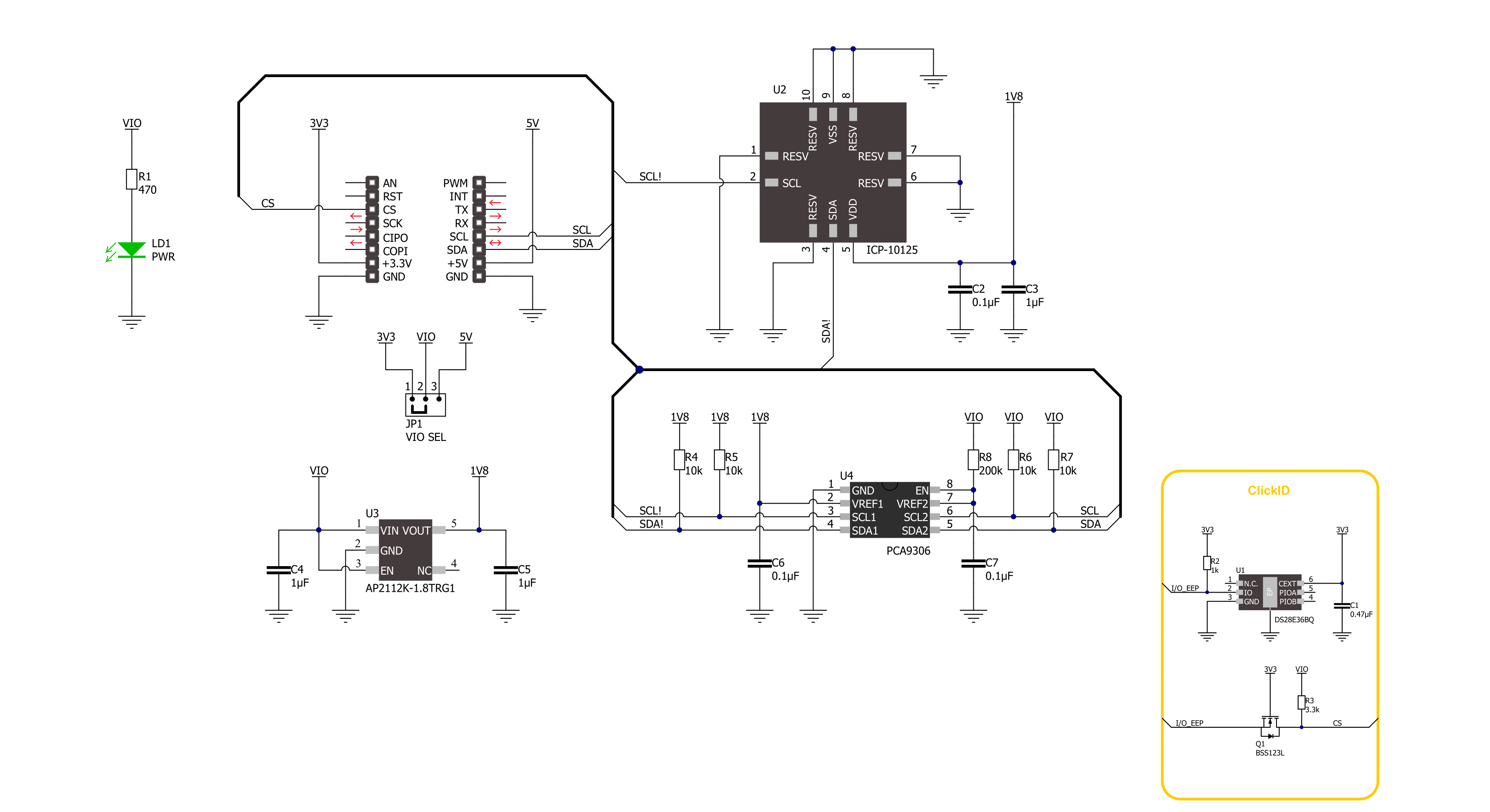
Barometer 12 Click is based on the ICP-10125, a high-accuracy, low-power, 10-atm waterproof barometric pressure and temperature sensor from TDK InvenSense. It is a very accurate sensor and can measure pressure differences with an accuracy of ±1 Pa, enabling altitude measurement differentials as small as 8.5 cm, less than the height of a single stair step. In addition to high accuracy, this sensor consumes only 1.3μA at 1Hz, making it ideal for battery-powered applications.
According to the datasheet table, the sensor performs best with the recommended temperature and pressure range. The sensor works at 1.8V, which it gets from the AP2112, a CMOS LDO regulator from Diodes Incorporated. Barometer 12 Click uses a standard 2-Wire I2C interface to communicate with the host MCU, supporting clock frequency up to 400KHz. To allow safe sensor operation on both 5V and 3.3V voltage logic, this Click board™ features the PCA9306, a
dual bidirectional I2C bus and SMBus voltage-level translator from Texas Instruments. This Click board™ can operate with either 3.3V or 5V logic voltage levels selected via the VIO SEL jumper. This way, both 3.3V and 5V capable MCUs can use the communication lines properly. Also, this Click board™ comes equipped with a library containing easy-to-use functions and an example code that can be used as a reference for further development.

Features overview
Development board
Clicker 4 for STM32F4 is a compact development board designed as a complete solution that you can use to quickly build your own gadgets with unique functionalities. Featuring an STM32F407VGT6 MCU, four mikroBUS™ sockets for Click boards™ connectivity, power management, and more, it represents a perfect solution for the rapid development of many different types of applications. At its core is an STM32F407VGT6 MCU, a powerful microcontroller by STMicroelectronics based on the high-performance
Arm® Cortex®-M4 32-bit processor core operating at up to 168 MHz frequency. It provides sufficient processing power for the most demanding tasks, allowing Clicker 4 to adapt to any specific application requirements. Besides two 1x20 pin headers, four improved mikroBUS™ sockets represent the most distinctive connectivity feature, allowing access to a huge base of Click boards™, growing on a daily basis. Each section of Clicker 4 is clearly marked, offering an intuitive and clean interface. This makes working with the
development board much simpler and, thus, faster. The usability of Clicker 4 doesn’t end with its ability to accelerate the prototyping and application development stages: it is designed as a complete solution that can be implemented directly into any project, with no additional hardware modifications required. Four mounting holes [4.2mm/0.165”] at all four corners allow simple installation by using mounting screws.

Microcontroller Overview
MCU Card / MCU

Architecture
ARM Cortex-M4
MCU Memory (KB)
10
Silicon Vendor
STMicroelectronics
Pin count
100
RAM (Bytes)
100
Used MCU Pins
mikroBUS™ mapper
Take a closer look
Click board™ Schematic
Step by step
Project assembly

Start by selecting your development board and Click board™. Begin with the Clicker 4 for STM32F4 as your development board.


Software Support
Library Description
This library contains API for Barometer 12 Click driver.
Key functions:
barometer12_inv_invpres_calib- Barometer 12 inverse process data function.barometer12_get_raw_data- Barometer 12 get RAW data function.barometer12_get_press_and_temp- Barometer 12 get pressure and temperature function.
Open Source
Code example
The complete application code and a ready-to-use project are available through the NECTO Studio Package Manager for direct installation in the NECTO Studio. The application code can also be found on the MIKROE GitHub account.
/*!
 * @file main.c
 * @brief Barometer 12 Click example
 *
 * # Description
 * This library contains API for the Barometer 12 Click driver.
 * The library initializes and defines the I2C bus drivers
 * to write and read data from registers.
 * This demo application shows an example of
 * atmospheric pressure and temperature measurement.
 *
 * The demo application is composed of two sections :
 *
 * ## Application Init
 * The initialization of the I2C module and log UART.
 * After driver initialization and default settings,
 * the app display device ID.
 *
 * ## Application Task
 * This is an example that shows the use of a Barometer 12 Click board™.
 * Logs the atmospheric pressure [ Pa ] and temperature [ degree Celsius ] data.
 * Results are being sent to the Usart Terminal where you can track their changes.
 *
 * @author Stefan Ilic
 *
 */

#include "board.h"
#include "log.h"
#include "barometer12.h"

static barometer12_t barometer12;
static log_t logger;

void application_init ( void )
{
    log_cfg_t log_cfg;  /**< Logger config object. */
    barometer12_cfg_t barometer12_cfg;  /**< Click config object. */

    /**
     * Logger initialization.
     * Default baud rate: 115200
     * Default log level: LOG_LEVEL_DEBUG
     * @note If USB_UART_RX and USB_UART_TX
     * are defined as HAL_PIN_NC, you will
     * need to define them manually for log to work.
     * See @b LOG_MAP_USB_UART macro definition for detailed explanation.
     */
    LOG_MAP_USB_UART( log_cfg );
    log_init( &logger, &log_cfg );
    log_info( &logger, " Application Init " );

    // Click initialization.
    barometer12_cfg_setup( &barometer12_cfg );
    BAROMETER12_MAP_MIKROBUS( barometer12_cfg, MIKROBUS_1 );
    if ( I2C_MASTER_ERROR == barometer12_init( &barometer12, &barometer12_cfg ) )
    {
        log_error( &logger, " Communication init." );
        for ( ; ; );
    }

    if ( BAROMETER12_ERROR == barometer12_default_cfg ( &barometer12 ) )
    {
        log_error( &logger, " Default configuration." );
        for ( ; ; );
    }
    Delay_ms ( 100 );

    static uint16_t device_id;
    err_t err_flag = barometer12_get_device_id( &barometer12, &device_id );
    if ( BAROMETER12_ERROR == err_flag )
    {
        log_error( &logger, " Communication Error. " );
        log_info( &logger, " Please, run program again... " );

        for ( ; ; );
    }
    log_printf( &logger, " Device ID   : 0x%.4X \r\n", device_id );
    log_printf( &logger, "----------------------------\r\n" );
    Delay_ms ( 1000 );

    log_info( &logger, " Application Task " );
}

void application_task ( void )
{
    float pressure;
    float temperature;

    barometer12_get_press_and_temp( &barometer12, &pressure, &temperature );
    log_printf( &logger, " Pressure    : %.2f Pa\r\n", pressure );
    log_printf( &logger, " Temperature : %.2f C\r\n", temperature );
    log_printf( &logger, "----------------------------\r\n" );
    Delay_ms ( 1000 );
}

int main ( void )
{
    /* Do not remove this line or clock might not be set correctly. */
    #ifdef PREINIT_SUPPORTED
    preinit();
    #endif

    application_init( );

    for ( ; ; )
    {
        application_task( );
    }

    return 0;
}

// ------------------------------------------------------------------------ END
Additional Support
Resources
Category:Pressure


