Navigate your world with NEO-M8M and STM32F407VGT6
Discover new horizons, effortlessly guided

Published Dec 29, 2023
Click board™
GNSS 5 Click
Dev. board
Clicker 4 for STM32F4
Compiler
NECTO Studio
MCU
STM32F407VGT6
Stay ahead of the game and build smart navigation applications - optimized for speed, precision, and reliability
A
A
Hardware Overview
How does it work?
GNSS 5 Click is based on the NEO-M8N, a GNSS receiver module from u-blox. GNSS 5 click is designed to run on a 3.3V power supply. The click communicates with the target microcontroller over the I2C or UART interface, with additional functionality provided by the following pins on the mikroBUS™ line: RST, INT, and PWM. A USB interface (micro USB port), compatible with the USB version 2.0 FS (Full Speed, 12 Mbit/s), can be used for communication as an alternative to the UART. The USB port can also be used as a power supply if you need the click board™ to be a standalone device. The NEO-M8 series of concurrent GNSS modules are built on the
high-performing u-blox M8 GNSS engine in the industry-proven NEO form factor. The NEO-M8 series utilizes concurrent reception of up to three GNSS systems (GPS/Galileo with BeiDou or GLONASS), simultaneously recognizes multiple constellations, and provides outstanding positioning accuracy in scenarios involving urban canyons or weak signals. The u-blox NEO-M8 modules can also benefit from the u-blox AssistNow assistance service. The Online service provides GNNS broadcast parameters, e.g., ephemeris, almanac plus time, or rough position, to reduce the receiver’s time first to fix significantly and improve acquisition sensitivity. Hardware
Backup Mode - If the main supply voltage fails and a battery is connected to V_BCKP, parts of the receiver switch off, but the RTC still runs, providing a timing reference for the receiver. This operating mode enables all relevant data to be saved in the backup RAM to allow a hot or warm start later. This Click board™ can be operated only with a 3.3V logic voltage level. The board must perform appropriate logic voltage level conversion before using MCUs with different logic levels. Also, it comes equipped with a library containing functions and an example code that can be used as a reference for further development.

Features overview
Development board
Clicker 4 for STM32F4 is a compact development board designed as a complete solution that you can use to quickly build your own gadgets with unique functionalities. Featuring an STM32F407VGT6 MCU, four mikroBUS™ sockets for Click boards™ connectivity, power management, and more, it represents a perfect solution for the rapid development of many different types of applications. At its core is an STM32F407VGT6 MCU, a powerful microcontroller by STMicroelectronics based on the high-performance
Arm® Cortex®-M4 32-bit processor core operating at up to 168 MHz frequency. It provides sufficient processing power for the most demanding tasks, allowing Clicker 4 to adapt to any specific application requirements. Besides two 1x20 pin headers, four improved mikroBUS™ sockets represent the most distinctive connectivity feature, allowing access to a huge base of Click boards™, growing on a daily basis. Each section of Clicker 4 is clearly marked, offering an intuitive and clean interface. This makes working with the
development board much simpler and, thus, faster. The usability of Clicker 4 doesn’t end with its ability to accelerate the prototyping and application development stages: it is designed as a complete solution that can be implemented directly into any project, with no additional hardware modifications required. Four mounting holes [4.2mm/0.165”] at all four corners allow simple installation by using mounting screws.

Microcontroller Overview
MCU Card / MCU

Architecture
ARM Cortex-M4
MCU Memory (KB)
10
Silicon Vendor
STMicroelectronics
Pin count
100
RAM (Bytes)
100
You complete me!
Accessories
GNSS Active External Antenna is a unique multi-band type of antenna coming from u-Blox that is the perfect selection for high precision GNSS applications, which require highly accurate location abilities such as RTK. The ANN-MB-00 is a multi-band (L1, L2/E5b/B2I) active GNSS antenna with a 5m cable and SMA connector. The antenna supports GPS, GLONASS, Galileo, and BeiDou and includes a high-performance multi-band RHCP dual-feed patch antenna element, a built-in high-gain LNA with SAW pre-filtering, and a 5 m antenna cable with SMA connector, and is waterproof.

Used MCU Pins
mikroBUS™ mapper
Take a closer look
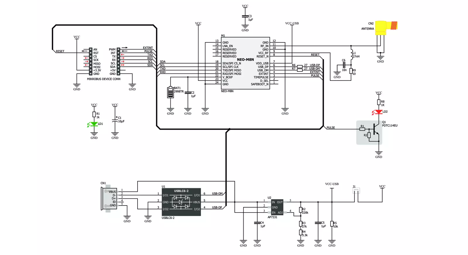
Click board™ Schematic
Step by step
Project assembly

Start by selecting your development board and Click board™. Begin with the Clicker 4 for STM32F4 as your development board.


Software Support
Library Description
This library contains API for GNSS 5 Click driver.
Key functions:
gnss5_generic_read- This function reads a desired number of data bytes by using UART serial interfacegnss5_clear_ring_buffers- This function clears UART tx and rx ring buffersgnss5_parse_gngga- This function parses the GNGGA data from the read response buffer
Open Source
Code example
The complete application code and a ready-to-use project are available through the NECTO Studio Package Manager for direct installation in the NECTO Studio. The application code can also be found on the MIKROE GitHub account.
/*!
 * @file main.c
 * @brief GNSS 5 Click Example.
 *
 * # Description
 * This example demonstrates the use of GNSS 5 Click by reading and displaying
 * the GPS coordinates.
 *
 * The demo application is composed of two sections :
 *
 * ## Application Init
 * Initializes the driver and logger.
 *
 * ## Application Task
 * Reads the received data, parses the GNGGA info from it, and once it receives the position fix
 * it will start displaying the coordinates on the USB UART.
 *
 * ## Additional Function
 * - static void gnss5_clear_app_buf ( void )
 * - static err_t gnss5_process ( gnss5_t *ctx )
 * - static void gnss5_parser_application ( char *rsp )
 *
 * @author Stefan Filipovic
 *
 */

#include "board.h"
#include "log.h"
#include "gnss5.h"
#include "string.h"

#define PROCESS_BUFFER_SIZE 200

static gnss5_t gnss5;
static log_t logger;

static char app_buf[ PROCESS_BUFFER_SIZE ] = { 0 };
static int32_t app_buf_len = 0;

/**
 * @brief GNSS 5 clearing application buffer.
 * @details This function clears memory of application buffer and reset its length.
 * @return None.
 * @note None.
 */
static void gnss5_clear_app_buf ( void );

/**
 * @brief GNSS 5 data reading function.
 * @details This function reads data from device and concatenates data to application buffer.
 * @param[in] ctx : Click context object.
 * See #gnss5_t object definition for detailed explanation.
 * @return @li @c  0 - Read some data.
 *         @li @c -1 - Nothing is read.
 * See #err_t definition for detailed explanation.
 * @note None.
 */
static err_t gnss5_process ( gnss5_t *ctx );

/**
 * @brief GNSS 5 parser application function.
 * @details This function parses GNSS data and logs it on the USB UART. It clears app and ring buffers
 * after successfully parsing data.
 * @param[in] ctx : Click context object.
 * See #gnss5_t object definition for detailed explanation.
 * @param[in] rsp Response buffer.
 * @return None.
 * @note None.
 */
static void gnss5_parser_application ( gnss5_t *ctx, char *rsp );

void application_init ( void )
{
    log_cfg_t log_cfg;  /**< Logger config object. */
    gnss5_cfg_t gnss5_cfg;  /**< Click config object. */

    /**
     * Logger initialization.
     * Default baud rate: 115200
     * Default log level: LOG_LEVEL_DEBUG
     * @note If USB_UART_RX and USB_UART_TX
     * are defined as HAL_PIN_NC, you will
     * need to define them manually for log to work.
     * See @b LOG_MAP_USB_UART macro definition for detailed explanation.
     */
    LOG_MAP_USB_UART( log_cfg );
    log_init( &logger, &log_cfg );
    log_info( &logger, " Application Init " );

    // Click initialization.
    gnss5_cfg_setup( &gnss5_cfg );
    GNSS5_MAP_MIKROBUS( gnss5_cfg, MIKROBUS_1 );
    if ( UART_ERROR == gnss5_init( &gnss5, &gnss5_cfg ) )
    {
        log_error( &logger, " Communication init." );
        for ( ; ; );
    }
    log_info( &logger, " Application Task " );
}

void application_task ( void )
{
    if ( GNSS5_OK == gnss5_process( &gnss5 ) )
    {
        if ( PROCESS_BUFFER_SIZE == app_buf_len )
        {
            gnss5_parser_application( &gnss5, app_buf );
        }
    }
}

int main ( void )
{
    /* Do not remove this line or clock might not be set correctly. */
    #ifdef PREINIT_SUPPORTED
    preinit();
    #endif

    application_init( );

    for ( ; ; )
    {
        application_task( );
    }

    return 0;
}

static void gnss5_clear_app_buf ( void )
{
    memset( app_buf, 0, app_buf_len );
    app_buf_len = 0;
}

static err_t gnss5_process ( gnss5_t *ctx )
{
    char rx_buf[ PROCESS_BUFFER_SIZE ] = { 0 };
    int32_t rx_size = 0;
    rx_size = gnss5_generic_read( ctx, rx_buf, PROCESS_BUFFER_SIZE );
    if ( rx_size > 0 )
    {
        int32_t buf_cnt = app_buf_len;
        if ( ( ( app_buf_len + rx_size ) > PROCESS_BUFFER_SIZE ) && ( app_buf_len > 0 ) )
        {
            buf_cnt = PROCESS_BUFFER_SIZE - ( ( app_buf_len + rx_size ) - PROCESS_BUFFER_SIZE );
            memmove ( app_buf, &app_buf[ PROCESS_BUFFER_SIZE - buf_cnt ], buf_cnt );
        }
        for ( int32_t rx_cnt = 0; rx_cnt < rx_size; rx_cnt++ )
        {
            if ( rx_buf[ rx_cnt ] )
            {
                app_buf[ buf_cnt++ ] = rx_buf[ rx_cnt ];
                if ( app_buf_len < PROCESS_BUFFER_SIZE )
                {
                    app_buf_len++;
                }
            }
        }
        return GNSS5_OK;
    }
    return GNSS5_ERROR;
}

static void gnss5_parser_application ( gnss5_t *ctx, char *rsp )
{
    char element_buf[ 100 ] = { 0 };
    if ( GNSS5_OK == gnss5_parse_gngga( rsp, GNSS5_GNGGA_LATITUDE, element_buf ) )
    {
        static uint8_t wait_for_fix_cnt = 0;
        if ( strlen( element_buf ) > 0 )
        {
            log_printf( &logger, "\r\n Latitude: %.2s degrees, %s minutes \r\n", element_buf, &element_buf[ 2 ] );
            gnss5_parse_gngga( rsp, GNSS5_GNGGA_LONGITUDE, element_buf );
            log_printf( &logger, " Longitude: %.3s degrees, %s minutes \r\n", element_buf, &element_buf[ 3 ] );
            memset( element_buf, 0, sizeof( element_buf ) );
            gnss5_parse_gngga( rsp, GNSS5_GNGGA_ALTITUDE, element_buf );
            log_printf( &logger, " Altitude: %s m \r\n", element_buf );
            wait_for_fix_cnt = 0;
        }
        else
        {
            if ( wait_for_fix_cnt % 5 == 0 )
            {
                log_printf( &logger, " Waiting for the position fix...\r\n\n" );
                wait_for_fix_cnt = 0;
            }
            wait_for_fix_cnt++;
        }
        gnss5_clear_ring_buffers( ctx );
        gnss5_clear_app_buf( );
    }
}

// ------------------------------------------------------------------------ END
Additional Support
Resources
Category:GPS/GNSS


