Enhance your safety by monitoring hydrogen gas leaks using MQ-8 and PIC18F97J94
Precise hydrogen sensing for all

Published Feb 12, 2024
Click board™
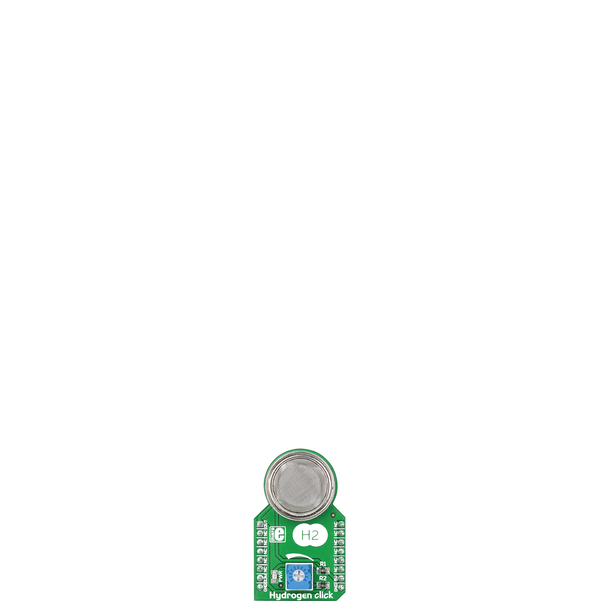
HYDROGEN Click
Dev. board
CLICKER 4 for PIC18F
Compiler
NECTO Studio
MCU
PIC18F97J94
By providing early detection of hydrogen leaks, this detection solution helps prevent the potential risks of fire, explosions, and asphyxiation, safeguarding the well-being of individuals and protecting property
A
A
Hardware Overview
How does it work?
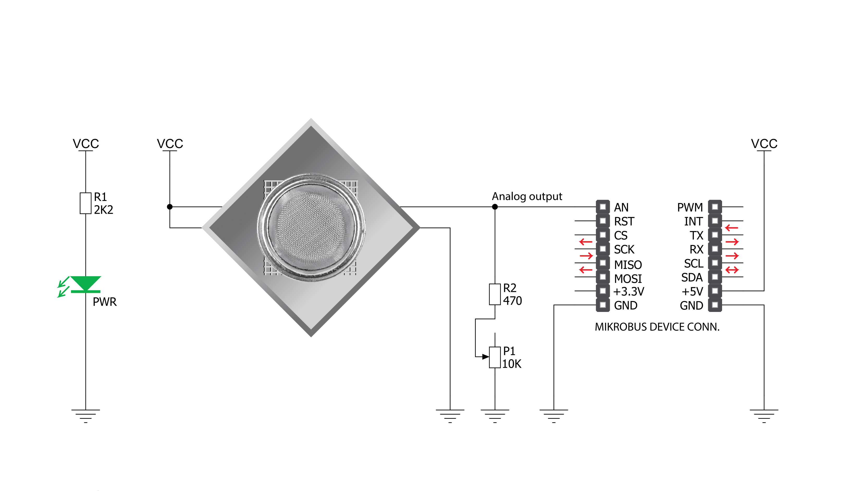
Hydrogen Click is based on the MQ-8, a hydrogen (H2) sensor from Zhengzhou Winsen Electronics Technology, which detects hydrogen's presence and concentration in the air. The gas sensing layer on the MQ-8 sensor unit is made of Tin dioxide (SnO2), which has lower conductivity in clean air. The conductivity increases as the levels of hydrogen rise. It has a high sensitivity to hydrogen in a wide range suitable for detecting it in concentrations from 100 to 10.000ppm. Besides a
binary indication of the presence of hydrogen, the MQ-8 also provides an analog representation of its concentration in the air sent directly to an analog pin of the mikroBUS™ socket labeled OUT. The analog output voltage the sensor provides varies in proportion to the hydrogen concentration; the higher the hydrogen concentration in the air, the higher the output voltage. Hydrogen Click has a small potentiometer that allows you to adjust the load resistance of the sensor circuit, to calibrate
the sensor for the environment in which you'll be using it. This Click board™ can be operated only with a 5V logic voltage level. The board must perform appropriate logic voltage level conversion before using MCUs with different logic levels. However, the Click board™ comes equipped with a library containing functions and an example code that can be used, as a reference, for further development.

Features overview
Development board
Clicker 4 for PIC18F is a compact development board designed as a complete solution to build your own gadgets with unique functionalities quickly. It features a PIC18F97J94MCU, four mikroBUS™ sockets for Click boards™ connectivity, power management, and more, and it is a perfect solution for the rapid development of many different types of applications. At its core is an 8-bit PIC18F97J94 MCU, a powerful microcontroller produced by Microchip, based on the high-performance CPU with two external clock modes, up to 64MHz. It
provides sufficient processing power for the most demanding tasks, allowing Clicker 4 to adapt to any specific application requirements. Besides two 1x20 pin headers, four improved mikroBUS™ sockets represent the most distinctive connectivity feature, allowing access to a huge base of Click boards™, growing on a daily basis. Each section of Clicker 4 is clearly marked, offering an intuitive and clean interface. This makes working with the development board much simpler and, thus, faster. The usability of Clicker 4 doesn’t end with its ability
to accelerate the prototyping and application development stages: it is designed as a complete solution that can be implemented directly into any project, with no additional hardware modifications required. Four mounting holes [4.2mm/0.165”] at all four corners allow simple installation by using mounting screws. For most applications, a nice, stylish casing is all that is needed to turn the Clicker 4 development board into a fully functional, custom design.

Microcontroller Overview
MCU Card / MCU
Architecture
PIC
MCU Memory (KB)
128
Silicon Vendor
Microchip
Pin count
100
RAM (Bytes)
3862
Used MCU Pins
mikroBUS™ mapper
Take a closer look
Click board™ Schematic
Step by step
Project assembly

Start by selecting your development board and Click board™. Begin with the CLICKER 4 for PIC18F as your development board.


Software Support
Library Description
This library contains API for Hydrogen Click driver.
Key functions:
hydrogen_read_an_pin_value- This function reads results of AD conversion of the AN pin.hydrogen_read_an_pin_voltage- This function reads results of AD conversion of the AN pin and converts them to proportional voltage level.
Open Source
Code example
The complete application code and a ready-to-use project are available through the NECTO Studio Package Manager for direct installation in the NECTO Studio. The application code can also be found on the MIKROE GitHub account.
/*!
 * @file main.c
 * @brief Hydrogen Click Example.
 *
 * # Description
 * The demo application shows the reading of the adc
 * values given by the sensors.
 *
 * The demo application is composed of two sections :
 *
 * ## Application Init
 * Configuring Clicks and log objects.
 *
 * ## Application Task
 * Reads the adc value and prints in two forms (DEC and HEX).
 *
 * @author Jelena Milosavljevic
 *
 */

#include "board.h"
#include "log.h"
#include "hydrogen.h"

static hydrogen_t hydrogen;   /**< Hydrogen Click driver object. */
static log_t logger;    /**< Logger object. */

void application_init ( void ) {
    log_cfg_t log_cfg;  /**< Logger config object. */
    hydrogen_cfg_t hydrogen_cfg;  /**< Click config object. */

    /**
     * Logger initialization.
     * Default baud rate: 115200
     * Default log level: LOG_LEVEL_DEBUG
     * @note If USB_UART_RX and USB_UART_TX
     * are defined as HAL_PIN_NC, you will
     * need to define them manually for log to work.
     * See @b LOG_MAP_USB_UART macro definition for detailed explanation.
     */
    LOG_MAP_USB_UART( log_cfg );
    log_init( &logger, &log_cfg );
    log_info( &logger, " Application Init " );

    // Click initialization.

    hydrogen_cfg_setup( &hydrogen_cfg );
    HYDROGEN_MAP_MIKROBUS( hydrogen_cfg, MIKROBUS_1);
    if ( hydrogen_init( &hydrogen, &hydrogen_cfg ) == ADC_ERROR ) {
        log_error( &logger, " Application Init Error. " );
        log_info( &logger, " Please, run program again... " );

        for ( ; ; );
    }
    log_info( &logger, " Application Task " );
}

void application_task ( void ) {
    uint16_t hydrogen_an_value = 0;

    if ( hydrogen_read_an_pin_value ( &hydrogen, &hydrogen_an_value ) != ADC_ERROR ) {
        log_printf( &logger, " ADC Value : %u\r\n", hydrogen_an_value );
    }

    float hydrogen_an_voltage = 0;

    if ( hydrogen_read_an_pin_voltage ( &hydrogen, &hydrogen_an_voltage ) != ADC_ERROR ) {
        log_printf( &logger, " AN Voltage : %.3f[V]\r\n\n", hydrogen_an_voltage );
    }

    Delay_ms ( 1000 );
}

int main ( void )
{
    /* Do not remove this line or clock might not be set correctly. */
    #ifdef PREINIT_SUPPORTED
    preinit();
    #endif

    application_init( );

    for ( ; ; )
    {
        application_task( );
    }

    return 0;
}

// ------------------------------------------------------------------------ END
Additional Support
Resources
Category:Gas


