Connect devices over short distances using B102C and PIC32MX460F512L
Bluetooth 5.0 (BLE) communication for advanced connectivity and energy efficiency

Published Sep 02, 2024
Click board™
B102C Click
Dev. board
Explorer 16/32 development board
Compiler
NECTO Studio
MCU
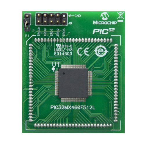
PIC32MX460F512L
Complete RF solution with an integrated 2.4GHz antenna for applications like beacons, building automation, and remote control toys
A
A
Hardware Overview
How does it work?
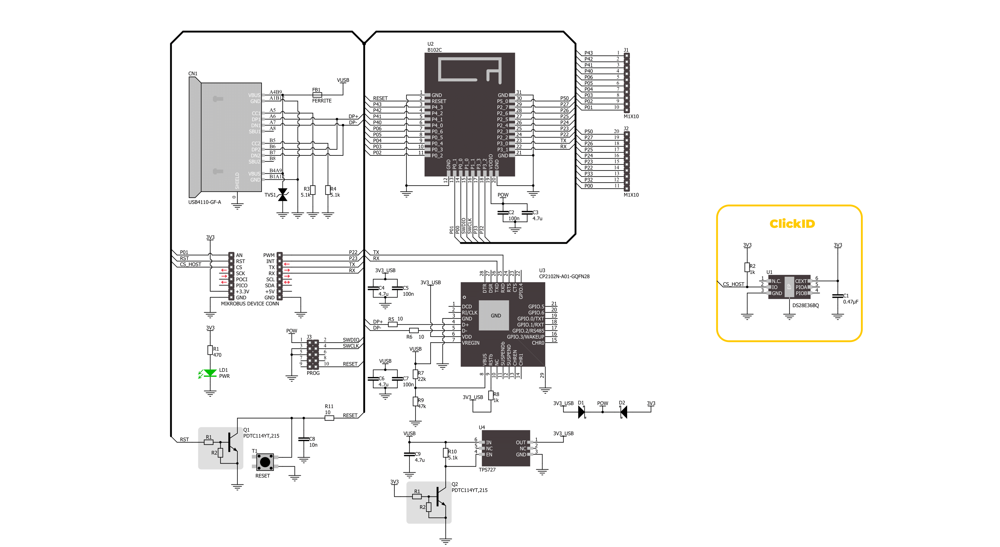
B102C Click is based on the B102C, a Bluetooth 5.0 (BLE) module from Amphenol. This module is built around the Realtek RTL8762CMF, offering BLE v5.0 support, a robust 20MHz Arm® Cortex® M4F processor, and exceptional power efficiency. It provides a complete RF solution with an integrated antenna operating in the 2.4GHz range (2402 - 2480MHz), along with a low-power crystal that optimizes power consumption by enabling advanced power-saving modes. Ideal for various applications, B102C Click can be used in beacons, building automation, remote control toys, lighting products, and many more. The B102C module comes preloaded with Amphenol firmware, supporting Bluetooth Low Energy Serial Port Service and simultaneous peripheral and central roles, all configurable through AT commands. It also allows full flexibility in adding custom applications on its built-in Cortex-M4 with 4Mbits of Flash, 4Kb eFuse, and 160KB SRAM. Regarding
the board's connectivity features, this Click board™ uses a UART interface for communication with the host MCU, using standard UART RX and TX pins to exchange AT commands. By default, it communicates at a baud rate of 115200bps. Additionally, the Click board™ is equipped with a USB Type-C connector, allowing power supply and configuration via a PC. This is achieved by the CP2102, a highly integrated USB-to-UART bridge, and a TPS727 LDO regulator, which provides the necessary 3.3V power supply for the module out of the USB supply. Additionally, on the left side of the board, there is an unpopulated PROG header that provides full support for debugging and programming. This header allows the user to utilize a Serial Wire Debug (SWD) interface for programming and debugging via the SWD interface pins. Along with the communication and control pins, this Click board™ also includes a reset pin (RST) and a RESET button, enabling easy module
resetting. All GPIO pins of the module are routed to two unpopulated J1 and J2 headers. These pins are fully programmable, with selectable pull-up and pull-down resistors for each pin. They retain their last state when the system enters Sleep mode and allow the module to be awakened by any GPIO while in Sleep mode. Three of these pins are also routed to the mikroBUS™ socket (P01, P22, and P23) to the AN, PWM, and INT default positions, allowing users to use these functions or configure them as desired, given that they are user-configurable pins. This Click board™ can be operated only with a 3.3V logic voltage level. The board must perform appropriate logic voltage level conversion before using MCUs with different logic levels. Also, it comes equipped with a library containing functions and an example code that can be used as a reference for further development.

Features overview
Development board
Explorer 16/32 development board is a flexible and convenient development, demonstration, and testing platform for 16-bit PIC24 MCUs, dsPIC® DSCs, and 32-bit PIC32 MCUs from Microchip Technology. It features all the necessary hardware to develop and debug a complete embedded application. The board accepts Processor Plug-In Modules (PIMs) designed for the Explorer 16 or Explorer 16/32 development board for easy device swapping. In addition to the hardware features provided by the board, hardware expansion is possible through the use of PICtail™ Plus
daughter cards and mikroBUS™ accessory boards. Coupled with the integrated PICkit™-On-Board (PKOB), MPLAB ICD In-Circuit Debugger real-time debug facilities enable faster evaluation and prototyping of applications. This development board supports all the Explorer PIMs. However, not all PIMs are supported by the PKOB. To check the list of supported and unsupported PIMs, refer to the PICkit™ On-Board 3 (PKOB3) Support List. For PIMs not on the PKOB3 support list, use the JP1 or J14 connectors to program the device with a newer generation programming tool. Explorer 16/32
development board offers only the main board, allowing customization of the other necessary components. Choose your PIM based on MCUs and DSCs under consideration from a wide range of Processor Plug-In Modules. This board is optimal for customers migrating from Classic Explorer 16 to the new Explorer 16/32 platform, while all the necessary additional components like Processor Plug-In Modules and PICtail™ Plus Daughter Boards are already available.

Microcontroller Overview
MCU Card / MCU
Architecture
PIC32
MCU Memory (KB)
512
Silicon Vendor
Microchip
Pin count
100
RAM (Bytes)
32768
Used MCU Pins
mikroBUS™ mapper
Take a closer look
Click board™ Schematic
Step by step
Project assembly

Start by selecting your development board and Click board™. Begin with the Explorer 16/32 development board as your development board.


Software Support
Library Description
This library contains API for B102C Click driver.
Key functions:
b102c_send_cmd- This function sends a specified command to the B102C Click module.b102c_send_cmd_with_params- This function sends a command with specified parameter to the click module.b102c_send_cmd_params_check- This function checks the command that is sent.
Open Source
Code example
The complete application code and a ready-to-use project are available through the NECTO Studio Package Manager for direct installation in the NECTO Studio. The application code can also be found on the MIKROE GitHub account.
/*!
 * @file main.c
 * @brief B102C Click Example.
 *
 * # Description
 * This example demonstrates the use of B102C Click board by processing
 * the incoming data and displaying them on the USB UART.
 *
 * The demo application is composed of two sections :
 *
 * ## Application Init
 * Initializes the driver, then performs a factory reset and sets the local device name.
 *
 * ## Application Task
 * Reads and processes all incoming data and displays them on the USB UART.
 *
 * ## Additional Function
 * - static void b102c_clear_app_buf ( void )
 * - static void b102c_log_app_buf ( void )
 * - static err_t b102c_process ( b102c_t *ctx )
 * - static err_t b102c_rsp_check ( b102c_t *ctx, uint8_t *response )
 * - static void b102c_error_check( err_t error_flag )
 *
 * @note
 * For communication with B102C Click use the android application on the link:
 * https://play.google.com/store/apps/details?id=com.macdom.ble.blescanner
 *
 * @author Stefan Ilic
 *
 */

#include "board.h"
#include "log.h"
#include "b102c.h"

// Application buffer size
#define APP_BUFFER_SIZE             500
#define PROCESS_BUFFER_SIZE         200

static b102c_t b102c;
static log_t logger;

static uint8_t app_buf[ APP_BUFFER_SIZE ] = { 0 };
static int32_t app_buf_len = 0;
static err_t app_error_flag;

/**
 * @brief B102C clearing application buffer.
 * @details This function clears memory of application buffer and reset its length.
 * @note None.
 */
static void b102c_clear_app_buf ( void );

/**
 * @brief B102C log application buffer.
 * @details This function logs data from application buffer to USB UART.
 * @note None.
 */
static void b102c_log_app_buf ( void );

/**
 * @brief B102C data reading function.
 * @details This function reads data from device and concatenates data to application buffer.
 * @param[in] ctx : Click context object.
 * See #b102c_t object definition for detailed explanation.
 * @return @li @c  0 - Read some data.
 *         @li @c -1 - Nothing is read.
 * See #err_t definition for detailed explanation.
 * @note None.
 */
static err_t b102c_process ( b102c_t *ctx );

/**
 * @brief B102C response read function.
 * @details This function reads the response of the sent command and writes it on the USB UART.
 * @param[in] ctx : Click context object.
 * See #b102c_t object definition for detailed explanation.
 * @param[in] response : Expected response.
 * @return @li @c  0 - Response OK.
 *         @li @c -1 - Response ERROR.
 * See #err_t definition for detailed explanation.
 * @note None.
 */
static err_t b102c_rsp_check ( b102c_t *ctx, uint8_t *response );

/**
 * @brief Check for errors.
 * @details This function checks for different types of
 * errors and logs them on UART or logs the response if no errors occured.
 * @param[in] error_flag : Response to be checked.
 * @note None.
 */
static void b102c_error_check( err_t error_flag );

void application_init ( void )
{
    log_cfg_t log_cfg;  /**< Logger config object. */
    b102c_cfg_t b102c_cfg;  /**< Click config object. */

    /**
     * Logger initialization.
     * Default baud rate: 115200
     * Default log level: LOG_LEVEL_DEBUG
     * @note If USB_UART_RX and USB_UART_TX
     * are defined as HAL_PIN_NC, you will
     * need to define them manually for log to work.
     * See @b LOG_MAP_USB_UART macro definition for detailed explanation.
     */
    LOG_MAP_USB_UART( log_cfg );
    log_init( &logger, &log_cfg );
    log_info( &logger, " Application Init " );

    // Click initialization.
    b102c_cfg_setup( &b102c_cfg );
    B102C_MAP_MIKROBUS( b102c_cfg, MIKROBUS_1 );
    if ( UART_ERROR == b102c_init( &b102c, &b102c_cfg ) )
    {
        log_error( &logger, " Communication init." );
        for ( ; ; );
    }
    Delay_ms ( 100 );

    log_printf( &logger, " Software reset. \r\n" );
    b102c_send_cmd( &b102c, B102C_CMD_RESET );
    app_error_flag = b102c_rsp_check( &b102c, B102C_RSP_READY );

    log_printf( &logger, " Factory reset. \r\n" );
    b102c_send_cmd( &b102c, B102C_CMD_DEFAULT );
    app_error_flag = b102c_rsp_check( &b102c, B102C_RSP_READY );

    log_printf( &logger, " Set device name. \r\n" );
    #define DEVICE_NAME             "B102C Click"
    b102c_send_cmd_with_params( &b102c, B102C_CMD_NAME, DEVICE_NAME );
    app_error_flag = b102c_rsp_check( &b102c, B102C_RSP_OK );

    log_printf( &logger, " Set Auto broadcast mode. \r\n" );
    #define AUTO_BROADCAST          "1"
    b102c_send_cmd_with_params( &b102c, B102C_CMD_ADVMOD, AUTO_BROADCAST );
    app_error_flag = b102c_rsp_check( &b102c, B102C_RSP_OK );

    log_info( &logger, " Application Task " );
    log_printf( &logger, " Connect to device. " );
}

void application_task ( void )
{
    if ( B102C_OK == b102c_process( &b102c ) )
    {
        b102c_log_app_buf( );
        b102c_clear_app_buf( );
    }
}

int main ( void )
{
    /* Do not remove this line or clock might not be set correctly. */
    #ifdef PREINIT_SUPPORTED
    preinit();
    #endif

    application_init( );

    for ( ; ; )
    {
        application_task( );
    }

    return 0;
}

static void b102c_clear_app_buf ( void )
{
    memset( app_buf, 0, app_buf_len );
    app_buf_len = 0;
}

static void b102c_log_app_buf ( void )
{
    for ( int32_t buf_cnt = 0; buf_cnt < app_buf_len; buf_cnt++ )
    {
        log_printf( &logger, "%c", app_buf[ buf_cnt ] );
    }
}

static err_t b102c_process ( b102c_t *ctx )
{
    uint8_t rx_buf[ PROCESS_BUFFER_SIZE ] = { 0 };
    int32_t overflow_bytes = 0;
    int32_t rx_cnt = 0;
    int32_t rx_size = b102c_generic_read( ctx, rx_buf, PROCESS_BUFFER_SIZE );
    if ( ( rx_size > 0 ) && ( rx_size <= APP_BUFFER_SIZE ) )
    {
        if ( ( app_buf_len + rx_size ) > APP_BUFFER_SIZE )
        {
            overflow_bytes = ( app_buf_len + rx_size ) - APP_BUFFER_SIZE;
            app_buf_len = APP_BUFFER_SIZE - rx_size;
            memmove ( app_buf, &app_buf[ overflow_bytes ], app_buf_len );
            memset ( &app_buf[ app_buf_len ], 0, overflow_bytes );
        }
        for ( rx_cnt = 0; rx_cnt < rx_size; rx_cnt++ )
        {
            if ( rx_buf[ rx_cnt ] )
            {
                app_buf[ app_buf_len++ ] = rx_buf[ rx_cnt ];
            }
        }
        return B102C_OK;
    }
    return B102C_ERROR;
}

static err_t b102c_rsp_check ( b102c_t *ctx, uint8_t *response )
{
    uint16_t timeout_cnt = 0;
    uint16_t timeout = 50000;

    err_t error_flag = b102c_process( ctx );
    if ( ( error_flag != 0 ) && ( error_flag != -1 ) )
    {
        return error_flag;
    }

    while ( ( strstr( app_buf, response ) == 0 ) && ( strstr( app_buf, B102C_RSP_ERROR ) == 0 ) )
    {
        error_flag = b102c_process( ctx );
        if ( ( error_flag != 0 ) && ( error_flag != -1 ) )
        {
            return error_flag;
        }

        timeout_cnt++;
        if ( timeout_cnt > timeout )
        {
            return B102C_TIMEOUT;
        }

        Delay_ms ( 1 );
    }

    for ( int32_t buf_cnt = 0; buf_cnt < app_buf_len; buf_cnt++ )
    {
        log_printf( &logger, "%c", app_buf[ buf_cnt ] );
    }
    log_printf( &logger, "\r\n" );
    b102c_clear_app_buf( );
    Delay_ms ( 500 );

    log_printf( &logger, "-----------------------------------\r\n" );
}

static void b102c_error_check( err_t error_flag )
{
    if ( ( error_flag != 0 ) && ( error_flag != B102C_ERROR ) )
    {
        switch ( error_flag )
        {
            case B102C_OVERFLOW:
            {
                log_error( &logger, " Overflow!" );
                break;
            }
            case B102C_TIMEOUT:
            {
                log_error( &logger, " Timeout!" );
                break;
            }
            default:
            {
                break;
            }
        }
    }
}


// ------------------------------------------------------------------------ END
Additional Support
Resources
Category:BT/BLE


