Provide reliable and secure wireless connectivity for your embedded applications with Calypso (2610011025000) and PIC18F57Q43
Calypso WLAN module for communication over a wireless network using the IEEE 802.11 b/g/n standard

Published Sep 30, 2024
Click board™
Calypso Click
Dev. board
Curiosity Nano with PIC18F57Q43
Compiler
NECTO Studio
MCU
PIC18F57Q43
Ideal for cloud-connected systems requiring long-term low-power battery operation
A
A
Hardware Overview
How does it work?
Calypso Click is based on the WIRL-WIFS Calypso (2610011025000) WLAN module from Würth Elektronik, designed for wireless connectivity in embedded applications. This module adheres to the IEEE 802.11 b/g/n standards and comes equipped with a fully integrated TCP/IP stack, making it a versatile solution for WiFi communication. With its WiFi certification (ID: WFA81685), Calypso ensures compliance with industry standards, offering reliable application performance. The module is designed with edge castellated connections and a smart antenna configuration, providing easy integration into any system. It includes an intuitive AT-style command interface, simplifying configuration and control. Supporting both IPv4 and IPv6, Calypso comes preloaded with a variety of networking protocols such as SNTP, DHCPv4, DHCPv6, mDNS, HTTP(S), and MQTT, enabling efficient and secure data exchange. Calypso Click is built with advanced security features, including the ability to handle up to six secure sockets simultaneously and secure boot, storage, and over-the-air (OTA) updates. These features ensure a high level of security, making it an ideal choice for IoT applications requiring safe and reliable cloud connectivity. Calypso provides robust wireless connectivity with minimal power consumption, whether you are looking for a serial cable replacement or a low-power solution for IoT devices with moderate data throughput needs. This board is perfect for various applications, from industrial automation to smart home devices, where secure,
low-power wireless communication is essential. The Calypso module functions as a radio sub-system, providing WLAN communication capabilities. It interfaces with the host MCU via a UART connection, using standard RX and TX pins, along with hardware flow control through CTS and RTS pins. With a default communication speed of 921600bps, the module ensures smooth and efficient data transmission. The entire module can be configured and controlled using AT commands over the UART interface. Once configured, it independently manages WLAN connectivity, freeing up the host controller for other tasks. Additionally, custom firmware development can achieve standalone applications without a host. The Click board™ features a USB Type-C connector, enabling power supply and configuration through a PC. This is made possible by the CP2102N, a highly integrated USB-to-UART bridge, and the NCP1117 LDO regulator, which converts the USB supply to the required 3.3V for the module. In addition to this power method, the board also supports backup power from a coin battery located on the back, allowing for the previously mentioned standalone operation. In addition to the UART interface, this Click board™ also uses an I2C interface to control the I/O expander, the PCA9536, which manages specific module functions due to the limited number of mikroBUS™ pins. Through the expander, the following functions are controlled: AP0 and AP1, which are used to set the desired application mode such as AT command normal
mode, OTA, Provisioning, or Transparent mode; BOOT, which enables standard application boot when pulled to a LOW logic level during Start-Up; and RM2, a user-configurable remote GPIO function that allows for the configuration and control of GPIOs, including Input, Output, and PWM. In addition to the expander, these signals can be manually controlled via the SW1 switch, with RM1 being managed instead of RM2 through the switch. The signal with the same function, RM0, can be controlled via the mikroBUS™ socket. This board is equipped with several additional features that enhance its functionality. It includes a reset pin (RST) and a RESET button for resetting the module, as well as a wake-up pin (WUP) to wake the module from Sleep mode. The board has two LED indicators for visual feedback: a green (LD2) and a blue (LD3) LED, both signaling the module’s operational statuses. Additionally, users can choose between the onboard PCB antenna, ideal for compact designs, or an external antenna for long-range applications, made possible through the onboard ANT u.Fl connector. This Click board™ can be operated only with a 3.3V logic voltage level. The board must perform appropriate logic voltage level conversion before using MCUs with different logic levels. Also, it comes equipped with a library containing functions and an example code that can be used as a reference for further development.

Features overview
Development board
PIC18F57Q43 Curiosity Nano evaluation kit is a cutting-edge hardware platform designed to evaluate microcontrollers within the PIC18-Q43 family. Central to its design is the inclusion of the powerful PIC18F57Q43 microcontroller (MCU), offering advanced functionalities and robust performance. Key features of this evaluation kit include a yellow user LED and a responsive
mechanical user switch, providing seamless interaction and testing. The provision for a 32.768kHz crystal footprint ensures precision timing capabilities. With an onboard debugger boasting a green power and status LED, programming and debugging become intuitive and efficient. Further enhancing its utility is the Virtual serial port (CDC) and a debug GPIO channel (DGI
GPIO), offering extensive connectivity options. Powered via USB, this kit boasts an adjustable target voltage feature facilitated by the MIC5353 LDO regulator, ensuring stable operation with an output voltage ranging from 1.8V to 5.1V, with a maximum output current of 500mA, subject to ambient temperature and voltage constraints.

Microcontroller Overview
MCU Card / MCU

Architecture
PIC
MCU Memory (KB)
128
Silicon Vendor
Microchip
Pin count
48
RAM (Bytes)
8196
You complete me!
Accessories
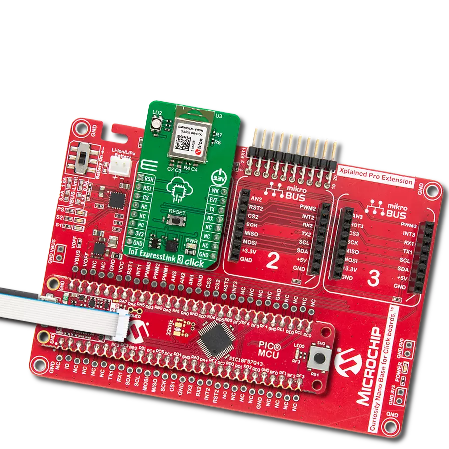
Curiosity Nano Base for Click boards is a versatile hardware extension platform created to streamline the integration between Curiosity Nano kits and extension boards, tailored explicitly for the mikroBUS™-standardized Click boards and Xplained Pro extension boards. This innovative base board (shield) offers seamless connectivity and expansion possibilities, simplifying experimentation and development. Key features include USB power compatibility from the Curiosity Nano kit, alongside an alternative external power input option for enhanced flexibility. The onboard Li-Ion/LiPo charger and management circuit ensure smooth operation for battery-powered applications, simplifying usage and management. Moreover, the base incorporates a fixed 3.3V PSU dedicated to target and mikroBUS™ power rails, alongside a fixed 5.0V boost converter catering to 5V power rails of mikroBUS™ sockets, providing stable power delivery for various connected devices.

Used MCU Pins
mikroBUS™ mapper
Take a closer look
Click board™ Schematic

Step by step
Project assembly

Start by selecting your development board and Click board™. Begin with the Curiosity Nano with PIC18F57Q43 as your development board.


Track your results in real time
Application Output
1. Application Output - In Debug mode, the 'Application Output' window enables real-time data monitoring, offering direct insight into execution results. Ensure proper data display by configuring the environment correctly using the provided tutorial.

2. UART Terminal - Use the UART Terminal to monitor data transmission via a USB to UART converter, allowing direct communication between the Click board™ and your development system. Configure the baud rate and other serial settings according to your project's requirements to ensure proper functionality. For step-by-step setup instructions, refer to the provided tutorial.

3. Plot Output - The Plot feature offers a powerful way to visualize real-time sensor data, enabling trend analysis, debugging, and comparison of multiple data points. To set it up correctly, follow the provided tutorial, which includes a step-by-step example of using the Plot feature to display Click board™ readings. To use the Plot feature in your code, use the function: plot(*insert_graph_name*, variable_name);. This is a general format, and it is up to the user to replace 'insert_graph_name' with the actual graph name and 'variable_name' with the parameter to be displayed.

Software Support
Library Description
This library contains API for Calypso Click driver.
Key functions:
calypso_set_app_mode- This function is used to set selected APP mode of Calypso click board.calypso_hw_reset- This function is used to perform HW reset.calypso_send_cmd- This function is used to send a desired command.
Open Source
Code example
The complete application code and a ready-to-use project are available through the NECTO Studio Package Manager for direct installation in the NECTO Studio. The application code can also be found on the MIKROE GitHub account.
/*!
 * @file main.c
 * @brief Calypso Click Example.
 *
 * # Description
 * This example demonstrates the use of Calypso Click board by processing
 * the incoming data and displaying them on the USB UART.
 *
 * The demo application is composed of two sections :
 *
 * ## Application Init
 * Initializes the driver and places AT command mode, tests the communication,
 * and after that restarts the device, and performs example configuration.
 *
 * ## Application Task
 * It creates a connection to the TCP-UDP echo server, sends a message to it reads it back,
 * displaces it on the UART terminal, and then closes the connection.
 *
 * ## Additional Function
 * - static void calypso_clear_app_buf ( void )
 * - static void calypso_log_app_buf ( void )
 * - static err_t calypso_process ( void )
 * - static err_t calypso_rsp_check ( uint8_t *rsp )
 * - static void calypso_error_check ( err_t error_flag )
 * - static void calypso_configure_for_example ( void )
 * - static void calypso_example ( void )
 *
 * @author MikroE Team
 *
 */

#include "board.h"
#include "log.h"
#include "calypso.h"
#include "conversions.h"

// Message content
#define MESSAGE_CONTENT                     "Calypso Click board - demo example."

// TCP/UDP example parameters
#define REMOTE_IP                           "77.46.162.162" // TCP/UDP echo server IP address
#define REMOTE_PORT                         "51111"         // TCP/UDP echo server port

// WiFi parameters
#define WIFI_SSID                           "MikroE Public"
#define WIFI_PWD                            "mikroe.guest"

// Application buffer size
#define APP_BUFFER_SIZE                     256
#define PROCESS_BUFFER_SIZE                 256

static calypso_t calypso;
static log_t logger;
static err_t error_flag;

static uint8_t app_buf[ APP_BUFFER_SIZE ] = { 0 };
static int32_t app_buf_len = 0;

/**
 * @brief Calypso clearing application buffer.
 * @details This function clears memory of application buffer and reset its length.
 * @note None.
 */
static void calypso_clear_app_buf ( void );

/**
 * @brief Calypso log application buffer.
 * @details This function logs data from application buffer to USB UART.
 * @note None.
 */
static void calypso_log_app_buf ( void );

/**
 * @brief Calypso data reading function.
 * @details This function reads data from device and concatenates data to application buffer.
 * @return @li @c  0 - Read some data.
 *         @li @c -1 - Nothing is read.
 * See #err_t definition for detailed explanation.
 * @note None.
 */
static err_t calypso_process ( void );

/**
 * @brief Response check.
 * @details This function checks for response and
 * returns the status of response.
 * @param[in] rsp : Expected response.
 * @return @li @c  0 - OK response.
 *         @li @c -1 - Error response.
 *         @li @c -2 - Timeout error.
 *         @li @c -3 - Unknown error.
 * See #err_t definition for detailed explanation.
 */
static err_t calypso_rsp_check ( uint8_t *rsp );

/**
 * @brief Check for errors.
 * @details This function checks for different types of
 * errors and logs them on UART or logs the response if no errors occured.
 * @param[in] error_flag : Error flag to check.
 */
static void calypso_error_check ( err_t error_flag );

/**
 * @brief Calypso configure for example function.
 * @details This function is used to configure device for example.
 */
static void calypso_configure_for_example ( void );

/**
 * @brief Calypso execute example function.
 * @details This function executes TCP/UDP Example.
 */
static void calypso_example ( void );

void application_init ( void )
{
    log_cfg_t log_cfg;  /**< Logger config object. */
    calypso_cfg_t calypso_cfg;  /**< Click config object. */

    /**
     * Logger initialization.
     * Default baud rate: 115200
     * Default log level: LOG_LEVEL_DEBUG
     * @note If USB_UART_RX and USB_UART_TX
     * are defined as HAL_PIN_NC, you will
     * need to define them manually for log to work.
     * See @b LOG_MAP_USB_UART macro definition for detailed explanation.
     */
    LOG_MAP_USB_UART( log_cfg );
    log_init( &logger, &log_cfg );
    log_info( &logger, " Application Init " );

    // Click initialization.
    calypso_cfg_setup( &calypso_cfg );
    CALYPSO_MAP_MIKROBUS( calypso_cfg, MIKROBUS_1 );
    if ( UART_ERROR == calypso_init( &calypso, &calypso_cfg ) )
    {
        log_error( &logger, " Communication init." );
        for ( ; ; );
    }

    if ( CALYPSO_ERROR == calypso_default_cfg ( &calypso ) )
    {
        log_error( &logger, " Default configuration." );
        for ( ; ; );
    }

    calypso_configure_for_example( );

    log_info( &logger, " Application Task " );
}

void application_task ( void )
{
    calypso_example( );
}

int main ( void )
{
    /* Do not remove this line or clock might not be set correctly. */
    #ifdef PREINIT_SUPPORTED
    preinit();
    #endif

    application_init( );

    for ( ; ; )
    {
        application_task( );
    }

    return 0;
}

static void calypso_clear_app_buf ( void )
{
    memset( app_buf, 0, app_buf_len );
    app_buf_len = 0;
}

static void calypso_log_app_buf ( void )
{
    for ( int32_t buf_cnt = 0; buf_cnt < app_buf_len; buf_cnt++ )
    {
        log_printf( &logger, "%c", app_buf[ buf_cnt ] );
    }
}

static err_t calypso_process ( void )
{
    uint8_t rx_buf[ PROCESS_BUFFER_SIZE ] = { 0 };
    int32_t overflow_bytes = 0;
    int32_t rx_cnt = 0;
    int32_t rx_size = calypso_generic_read( &calypso, rx_buf, PROCESS_BUFFER_SIZE );
    if ( ( rx_size > 0 ) && ( rx_size <= APP_BUFFER_SIZE ) )
    {
        if ( ( app_buf_len + rx_size ) > APP_BUFFER_SIZE )
        {
            overflow_bytes = ( app_buf_len + rx_size ) - APP_BUFFER_SIZE;
            app_buf_len = APP_BUFFER_SIZE - rx_size;
            memmove ( app_buf, &app_buf[ overflow_bytes ], app_buf_len );
            memset ( &app_buf[ app_buf_len ], 0, overflow_bytes );
        }
        for ( rx_cnt = 0; rx_cnt < rx_size; rx_cnt++ )
        {
            if ( rx_buf[ rx_cnt ] )
            {
                app_buf[ app_buf_len++ ] = rx_buf[ rx_cnt ];
            }
        }
        return CALYPSO_OK;
    }
    return CALYPSO_ERROR;
}

static err_t calypso_rsp_check ( uint8_t *rsp )
{
    uint32_t timeout_cnt = 0;
    uint32_t timeout = 120000;
    calypso_clear_app_buf( );
    calypso_process( );
    while ( ( 0 == strstr( app_buf, rsp ) ) &&
            ( 0 == strstr( app_buf, CALYPSO_RSP_ERROR ) ) )
    {
        calypso_process( );
        if ( timeout_cnt++ > timeout )
        {
            calypso_clear_app_buf( );
            return CALYPSO_ERROR_TIMEOUT;
        }
        Delay_ms ( 1 );
    }
    Delay_ms ( 100 );
    calypso_process( );
    if ( strstr( app_buf, rsp ) )
    {
        return CALYPSO_OK;
    }
    else if ( strstr( app_buf, CALYPSO_RSP_ERROR ) )
    {
        return CALYPSO_ERROR_CMD;
    }
    else
    {
        return CALYPSO_ERROR_UNKNOWN;
    }
}

static void calypso_error_check ( err_t error_flag )
{
    switch ( error_flag )
    {
        case CALYPSO_OK:
        {
            calypso_log_app_buf( );
            break;
        }
        case CALYPSO_ERROR:
        {
            log_error( &logger, " Overflow!" );
            break;
        }
        case CALYPSO_ERROR_TIMEOUT:
        {
            log_error( &logger, " Timeout!" );
            break;
        }
        case CALYPSO_ERROR_CMD:
        {
            log_error( &logger, " ERROR Response!" );
            break;
        }
        case CALYPSO_ERROR_UNKNOWN:
        default:
        {
            log_error( &logger, " Unknown!" );
            break;
        }
    }
    log_printf( &logger, "- - - - - - - - - - - - - - - -\r\n" );
    Delay_ms ( 500 );
}

static void calypso_configure_for_example ( void )
{
    uint8_t command_data[ APP_BUFFER_SIZE ] = { 0 };

    log_printf( &logger, " Hardware reset. \r\n" );
    calypso_hw_reset( &calypso );
    error_flag = calypso_rsp_check( CALYPSO_RSP_READY );
    calypso_error_check( error_flag );

    log_printf( &logger, " Performing Test. \r\n" );
    calypso_send_cmd( &calypso, CALYPSO_CMD_AT_TEST );
    error_flag = calypso_rsp_check( CALYPSO_RSP_OK );
    calypso_error_check( error_flag );

    log_printf( &logger, " Setting WLAN Mode. \r\n" );
    calypso_send_cmd_with_par( &calypso, CALYPSO_CMD_AT_WLAN_SET_MODE, "STA" );
    error_flag = calypso_rsp_check( CALYPSO_RSP_OK );
    calypso_error_check( error_flag );

    #define SECURITY_TYPE           "WPA_WPA2"
    strcpy( command_data, WIFI_SSID );
    strcat( command_data, ",," );
    strcat( command_data, SECURITY_TYPE );
    strcat( command_data, "," );
    strcat( command_data, WIFI_PWD );
    strcat( command_data, ",,," );

    log_printf( &logger, " WLAN Connect. \r\n" );
    calypso_send_cmd_with_par( &calypso, CALYPSO_CMD_AT_WLAN_CONNECT, command_data );
    error_flag = calypso_rsp_check( CALYPSO_RSP_OK );
    calypso_error_check( error_flag );
    error_flag = calypso_rsp_check( CALYPSO_RSP_CONNECTED );
    calypso_error_check( error_flag );
}

static void calypso_example ( void )
{
    uint8_t command_data[ APP_BUFFER_SIZE ] = { 0 };
    uint8_t socket_num[ 4 ] = { 0 };
    uint8_t * __generic_ptr socket_num_buf = 0;
    #define SOCKET_OPEN             "+socket:"
    #define SOCKET_CONNECTED        "+connect:"
    #define SOCKET_FAMILY           "INET"
    #define SOCKET_TYPE             "STREAM"
    #define SOCKET_PROTOCOL_TCP     "TCP"
    #define SOCKET_PROTOCOL_UDP     "UDP"
    #define SOCKET_FORMAT_BINATY    "0"

    log_printf( &logger, " Create TCP socket. \r\n" );
    strcpy( command_data, SOCKET_FAMILY );
    strcat( command_data, "," );
    strcat( command_data, SOCKET_TYPE );
    strcat( command_data, "," );
    strcat( command_data, SOCKET_PROTOCOL_TCP );
    calypso_send_cmd_with_par( &calypso, CALYPSO_CMD_AT_SOCKET, command_data );
    error_flag = calypso_rsp_check( SOCKET_OPEN );
    calypso_error_check( error_flag );

    socket_num_buf = strstr( app_buf, SOCKET_OPEN ) + strlen ( SOCKET_OPEN );
    if ( socket_num_buf )
    {
        memcpy ( socket_num, socket_num_buf, 2 );
        if ( socket_num[ 1 ] < '0' || socket_num[ 1 ] > '9' )
        {
            socket_num[ 1 ] = 0;
        }
    }

    log_printf( &logger, " Connect to the TCP server. \r\n" );
    strcpy( command_data, socket_num );
    strcat( command_data, "," );
    strcat( command_data, SOCKET_FAMILY );
    strcat( command_data, "," );
    strcat( command_data, REMOTE_PORT );
    strcat( command_data, "," );
    strcat( command_data, REMOTE_IP );

    calypso_send_cmd_with_par( &calypso, CALYPSO_CMD_AT_CONNECT, command_data );
    error_flag = calypso_rsp_check( SOCKET_CONNECTED );
    calypso_error_check( error_flag );

    uint8_t message_len_buf[ 10 ] = { 0 };
    uint16_t message_len = strlen( MESSAGE_CONTENT );
    uint16_to_str( message_len, message_len_buf );
    l_trim( message_len_buf );
    r_trim( message_len_buf );

    log_printf( &logger, " Send data to the TCP server. \r\n" );
    strcpy( command_data, socket_num );
    strcat( command_data, "," );
    strcat( command_data, SOCKET_FORMAT_BINATY );
    strcat( command_data, "," );
    strcat( command_data, message_len_buf );
    strcat( command_data, "," );
    strcat( command_data, MESSAGE_CONTENT );
    calypso_send_cmd_with_par( &calypso, CALYPSO_CMD_AT_SEND, command_data );
    error_flag = calypso_rsp_check( CALYPSO_RSP_OK );
    calypso_error_check( error_flag );

    log_printf( &logger, " Read data from the TCP server. \r\n" );
    strcpy( command_data, socket_num );
    strcat( command_data, "," );
    strcat( command_data, SOCKET_FORMAT_BINATY );
    strcat( command_data, "," );
    strcat( command_data, message_len_buf );
    calypso_send_cmd_with_par( &calypso, CALYPSO_CMD_AT_RECV, command_data );
    error_flag = calypso_rsp_check( CALYPSO_RSP_OK );
    calypso_error_check( error_flag );

    log_printf( &logger, " Closing the TCP connection. \r\n" );
    strcpy( command_data, socket_num );
    calypso_send_cmd_with_par( &calypso, CALYPSO_CMD_AT_CLOSE, command_data );
    error_flag = calypso_rsp_check( CALYPSO_RSP_OK );
    calypso_error_check( error_flag );

    log_printf( &logger, " Create UDP socket. \r\n" );
    strcpy( command_data, SOCKET_FAMILY );
    strcat( command_data, "," );
    strcat( command_data, SOCKET_TYPE );
    strcat( command_data, "," );
    strcat( command_data, SOCKET_PROTOCOL_UDP );
    calypso_send_cmd_with_par( &calypso, CALYPSO_CMD_AT_SOCKET, command_data );
    error_flag = calypso_rsp_check( SOCKET_OPEN );
    calypso_error_check( error_flag );

    socket_num_buf = strstr( app_buf, SOCKET_OPEN ) + strlen ( SOCKET_OPEN );
    if ( socket_num_buf )
    {
        memcpy ( socket_num, socket_num_buf, 2 );
        if ( socket_num[ 1 ] < '0' || socket_num[ 1 ] > '9' )
        {
            socket_num[ 1 ] = 0;
        }
    }

    log_printf( &logger, " Connect to the UDP server. \r\n" );
    strcpy( command_data, socket_num );
    strcat( command_data, "," );
    strcat( command_data, SOCKET_FAMILY );
    strcat( command_data, "," );
    strcat( command_data, REMOTE_PORT );
    strcat( command_data, "," );
    strcat( command_data, REMOTE_IP );
    calypso_send_cmd_with_par( &calypso, CALYPSO_CMD_AT_CONNECT, command_data );
    error_flag = calypso_rsp_check( SOCKET_CONNECTED );
    calypso_error_check( error_flag );

    log_printf( &logger, " Send data to the UDP server. \r\n" );
    strcpy( command_data, socket_num );
    strcat( command_data, "," );
    strcat( command_data, SOCKET_FORMAT_BINATY );
    strcat( command_data, "," );
    strcat( command_data, message_len_buf );
    strcat( command_data, "," );
    strcat( command_data, MESSAGE_CONTENT );
    calypso_send_cmd_with_par( &calypso, CALYPSO_CMD_AT_SEND, command_data );
    error_flag = calypso_rsp_check( CALYPSO_RSP_OK );
    calypso_error_check( error_flag );

    log_printf( &logger, " Read data from the UDP server. \r\n" );
    strcpy( command_data, socket_num );
    strcat( command_data, "," );
    strcat( command_data, SOCKET_FORMAT_BINATY );
    strcat( command_data, "," );
    strcat( command_data, message_len_buf );
    calypso_send_cmd_with_par( &calypso, CALYPSO_CMD_AT_RECV, command_data );
    error_flag = calypso_rsp_check( CALYPSO_RSP_OK );
    calypso_error_check( error_flag );

    log_printf( &logger, " Closing the UDP connection. \r\n" );
    strcpy( command_data, socket_num );
    calypso_send_cmd_with_par( &calypso, CALYPSO_CMD_AT_CLOSE, command_data );
    error_flag = calypso_rsp_check( CALYPSO_RSP_OK );
    calypso_error_check( error_flag );

    Delay_ms ( 1000 );
    Delay_ms ( 1000 );
    Delay_ms ( 1000 );
    Delay_ms ( 1000 );
    Delay_ms ( 1000 );
}

// ------------------------------------------------------------------------ END
Additional Support
Resources
Category:WiFi