Make your music pop with TPA3138D2 and PIC18F57Q43
Amplify your groove - because your beats deserve to roar!

Published Feb 13, 2024
Click board™
AudioAmp 5 Click
Dev. board
Curiosity Nano with PIC18F57Q43
Compiler
NECTO Studio
MCU
PIC18F57Q43
Upgrade your audio setup and unleash the full potential of your speakers with our high-quality amplifier, designed to deliver powerful, clean, and distortion-free sound
A
A
Hardware Overview
How does it work?
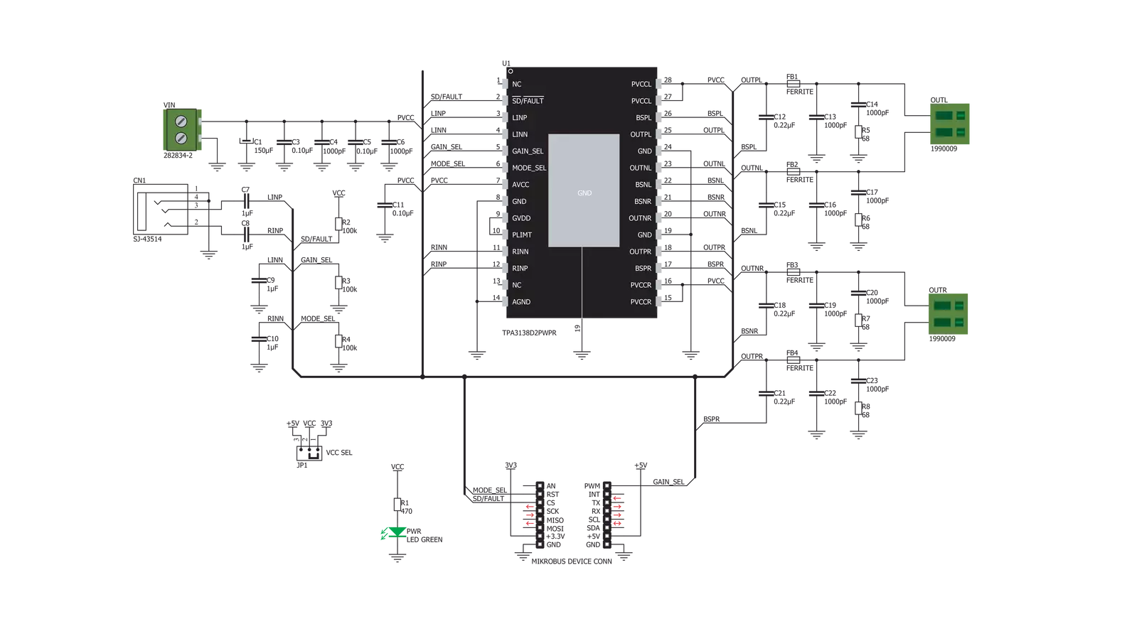
AudioAmp 5 Click is based on the TPA3138D2, an inductor-less stereo class-D audio amplifier from Texas Instruments. It has many features that make this IC an attractive solution for battery-powered and stand-alone active speakers. It is very flexible regarding the PSU voltage: it can work with voltages within the range of 3.5V to 14.4V. With only 3.5V at the PSU connector, it can still deliver 1W of power to a 6Ω load (per channel). However, its nominal operating voltage is 12V, reaching up to 10W of power to the connected 6Ω speaker, with only 1% of Total Harmonic Distortion (THD). The TPA3138D2 IC features a set of protections, including output short circuit, over-temperature, under-voltage, and over-voltage protection. These protections will be reported at the SD/FAULT (EN) I/O pin if any of these protections are activated. The TPA3138D2 IC can also detect a constant DC current at the output. When a DC detection event occurs, the outputs are turned OFF, protecting the connected speakers. Very often, a DC detection event can be triggered when the circuit is powered up, so it is advisable to hold the EN pin to a LOW logic level for a short period, preventing faulty DC detection reports and loud pops. The output stage of the TPA3138D2 operates in Bridge-Tied Load (BTL) topology. This means there are two outputs per channel: inverted and non-inverted (OUTN and OUTP). Class-D amplifier produces the sound by modulating the pulse-with of the output voltage. It offers a choice of two PWM modulation schemes,
selectable by the MODE_SEL pin of the IC. This pin is routed to the mikroBUS™ RST pin, labeled as MDS on this Click board™. By default, a resistor pulls the MDS pin to a LOW logic level. When the MDS pin is set to a LOW logic level, the TPA3138D2 uses the BD Modulation scheme. This scheme reduces the need for a typical LC reconstruction filter at the output. While there is no input, both OUTN and OUTP are in phase, with a 50% duty cycle. There is no current through the speaker in this case. The duty cycle will increase at the OUTP and decrease at the OUTN simultaneously when the positive half-phase of the audio signal is applied at the input. For the negative half-phase at the input, the opposite will happen. The greater the difference in pulse width, the greater the current through the connected speaker. When the MDS pin is set to a HIGH logic level, the TPA3138D2 uses the 1SPW Modulation scheme. This scheme allows low idle current and better overall efficiency at the expense of increased THD. Both OUTP and OUTN are held in phase at about 15% duty cycle. As the input signal is applied, one output is driven to the GND while the other output increases. The modulation takes place through this single output, reducing the switching losses. Again, the positive half-phase will cause the OUTN to be driven to GND, while the negative half-phase of the input signal causes the OUTP to be driven to GND. The SD/FAULT pin allows the host MCU to enable/disable outputs. Pulling this pin to a
LOW logic level makes the outputs muted, and the TPA3138D2 IC enters the low-current state, reducing the supply current to the absolute minimum level. Muting the TPA3138D2 before cutting down the power supply reduces the pops and clicks that might appear in this case. The SD/FAULT pin is routed to the mikroBUS™ CS pin labeled EN on this Click board™, and a resistor pulls it to a HIGH logic level. There is a selectable input gain on Audio Amp 5 click. Applying a LOW logic level to the GAIN_SEL pin sets the input gain to 20dB. A HIGH logic level sets the input gain to 26dB. This allows matching the input signal to reach the optimal output level. This pin is routed to the mikroBUS™ PWM pin labeled as GS and pulled to the LOW logic level by a resistor. The external PSU should be connected to the VIN terminal. A line-level audio source can be connected to the LINE IN 3.5mm jack stereo connector, while the speakers should be connected to the angled spring terminals labeled OUTL and OUTR. These terminals have their polarities marked on the top overlay. This Click board™ can operate with either 3.3V or 5V logic voltage levels selected via the VCC SEL jumper. This way, both 3.3V and 5V capable MCUs can use the communication lines properly. However, the Click board™ comes equipped with a library containing easy-to-use functions and an example code that can be used, as a reference, for further development.

Features overview
Development board
PIC18F57Q43 Curiosity Nano evaluation kit is a cutting-edge hardware platform designed to evaluate microcontrollers within the PIC18-Q43 family. Central to its design is the inclusion of the powerful PIC18F57Q43 microcontroller (MCU), offering advanced functionalities and robust performance. Key features of this evaluation kit include a yellow user LED and a responsive
mechanical user switch, providing seamless interaction and testing. The provision for a 32.768kHz crystal footprint ensures precision timing capabilities. With an onboard debugger boasting a green power and status LED, programming and debugging become intuitive and efficient. Further enhancing its utility is the Virtual serial port (CDC) and a debug GPIO channel (DGI
GPIO), offering extensive connectivity options. Powered via USB, this kit boasts an adjustable target voltage feature facilitated by the MIC5353 LDO regulator, ensuring stable operation with an output voltage ranging from 1.8V to 5.1V, with a maximum output current of 500mA, subject to ambient temperature and voltage constraints.

Microcontroller Overview
MCU Card / MCU

Architecture
PIC
MCU Memory (KB)
128
Silicon Vendor
Microchip
Pin count
48
RAM (Bytes)
8196
You complete me!
Accessories
Curiosity Nano Base for Click boards is a versatile hardware extension platform created to streamline the integration between Curiosity Nano kits and extension boards, tailored explicitly for the mikroBUS™-standardized Click boards and Xplained Pro extension boards. This innovative base board (shield) offers seamless connectivity and expansion possibilities, simplifying experimentation and development. Key features include USB power compatibility from the Curiosity Nano kit, alongside an alternative external power input option for enhanced flexibility. The onboard Li-Ion/LiPo charger and management circuit ensure smooth operation for battery-powered applications, simplifying usage and management. Moreover, the base incorporates a fixed 3.3V PSU dedicated to target and mikroBUS™ power rails, alongside a fixed 5.0V boost converter catering to 5V power rails of mikroBUS™ sockets, providing stable power delivery for various connected devices.

Used MCU Pins
mikroBUS™ mapper
Take a closer look
Click board™ Schematic
Step by step
Project assembly

Start by selecting your development board and Click board™. Begin with the Curiosity Nano with PIC18F57Q43 as your development board.


Software Support
Library Description
This library contains API for AudioAmp 5 Click driver.
Key functions:
audioamp5_mode_select- This function puts a device to the desired mode.audioamp5_gain_select- This function performs a desired gain selection.eaudioamp5_config_update- This function to update the configuration of the module.
Open Source
Code example
The complete application code and a ready-to-use project are available through the NECTO Studio Package Manager for direct installation in the NECTO Studio. The application code can also be found on the MIKROE GitHub account.
/*!
 * \file
 * \brief Audio Amp 5 Click example
 *
 * # Description
 * This example consist of sending special commands for audio output control,
 * selecting different output modes and turning on/off the audio output.
 *
 * The demo application is composed of two sections :
 *
 * ## Application Init
 * Initializes GPIO interface on the desired mikrobus selection,
 * and performs a device init configuration.
 *
 * ## Application Task
 * Checks the entered command and, if the command is valid,
 * performs a device configuration which the entered command determines.
 *
 *
 * \author Petar Suknjaja
 *
 */
// ------------------------------------------------------------------- INCLUDES

#include "board.h"
#include "log.h"
#include "audioamp5.h"

// ------------------------------------------------------------------ VARIABLES

static audioamp5_t audioamp5;
static log_t logger;

// ------------------------------------------------------ APPLICATION FUNCTIONS

void application_init ( void )
{
    log_cfg_t log_cfg;
    audioamp5_cfg_t cfg;

    /**
     * Logger initialization.
     * Default baud rate: 115200
     * Default log level: LOG_LEVEL_DEBUG
     * @note If USB_UART_RX and USB_UART_TX
     * are defined as HAL_PIN_NC, you will
     * need to define them manually for log to work.
     * See @b LOG_MAP_USB_UART macro definition for detailed explanation.
     */
    LOG_MAP_USB_UART( log_cfg );
    log_init( &logger, &log_cfg );
    log_info( &logger, "---- Application Init ----" );

    //  Click initialization.

    audioamp5_cfg_setup( &cfg );
    AUDIOAMP5_MAP_MIKROBUS( cfg, MIKROBUS_1 );
    audioamp5_init( &audioamp5, &cfg );

    audioamp5_default_cfg( &audioamp5 );
    log_printf( &logger, "** Audio Amp 5 is initialized **\r\n" );
    Delay_ms ( 500 );
}

void application_task ( void )
{
    //  Task implementation.

    audioamp5_gain_select( &audioamp5, AUDIOAMP5_GAIN_26DB );
    audioamp5_config_update( &audioamp5 );
    log_printf( &logger, "** Gain value is 26dB **\r\n" );

    Delay_ms ( 1000 );
    Delay_ms ( 1000 );
    Delay_ms ( 1000 );
    Delay_ms ( 1000 );
    Delay_ms ( 1000 );

    audioamp5_gain_select( &audioamp5, AUDIOAMP5_GAIN_20DB );
    audioamp5_config_update( &audioamp5 );
    log_printf( &logger, "** Gain value is 20dB **\r\n" );

    Delay_ms ( 1000 );
    Delay_ms ( 1000 );
    Delay_ms ( 1000 );
    Delay_ms ( 1000 );
    Delay_ms ( 1000 );
}

int main ( void )
{
    /* Do not remove this line or clock might not be set correctly. */
    #ifdef PREINIT_SUPPORTED
    preinit();
    #endif

    application_init( );

    for ( ; ; )
    {
        application_task( );
    }

    return 0;
}


// ------------------------------------------------------------------------ END
Additional Support
Resources
Category:Amplifier


