Strive for perfection in your projects using AD5142A and PIC18F57Q43
Say goodbye to analog limitations
Published Feb 13, 2024
Click board™
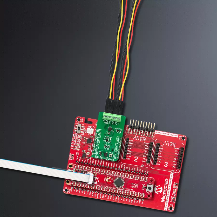
DIGI POT 12 Click
Dev. board
Curiosity Nano with PIC18F57Q43
Compiler
NECTO Studio
MCU
PIC18F57Q43
Maximize the potential of your electronic circuits by unlocking unparalleled precision with our digital potentiometer – the key to achieving peak performance and efficiency in every application.
A
A
Hardware Overview
How does it work?
DIGI POT 12 Click is based on the AD5142A, a dual-channel, 256-position nonvolatile digital potentiometer from Analog Devices. The resistor wiper position is determined by the RDAC register contents, which act as a scratchpad register, allowing unlimited changes of resistance settings. The scratchpad register can be programmed with any position setting using the standard I2C interface by loading the 16-bit data word. The nominal resistance of the RDAC between terminals A and terminals B (RAB) is 10KΩ with 8-bit RDAC latch data decoded to select one of the 256 possible wiper settings. When a desired position is found, this value can be stored in the onboard EEPROM memory; thus, the wiper position is always restored for subsequent power-ups. The EEPROM data can be read back, written
independently, and protected by software. This Click board™ communicates with MCU through a standard 2-Wire I2C interface and operates at Standard (100KHz) and Fast (400KHz) data transfer modes. The I2C address can be selected via the ADDR SEL jumpers with 0 selected by default. There is an RST pin for resetting the digital potentiometers RDAC registers from EEPROM, with active LOW logic. In addition, this Click board™ comes with the INDEP SEL jumper that allows you to choose between the potentiometer and the linear gain setting mode, with the potentiometer mode set by default (0). The linear gain setting mode of operation can control the potentiometer as two independent rheostats connected at a single point. Once the jumper is set, it can not be turned off by software. In
addition, there is a burst mode in which multiple data bytes can be sent to the host MCU. The Shutdown mode places the RDAC in a zero power consumption while the data in EEPROM remains. There is no polarity constraint between the B, W, and A on both terminals, but they can not be higher than the VCC (5V maximum) nor lower than the VSS (0V). This Click board™ can operate with either 3.3V or 5V logic voltage levels selected via the VCC SEL jumper. This way, both 3.3V and 5V capable MCUs can use the communication lines properly. Also, this Click board™ comes equipped with a library containing easy-to-use functions and an example code that can be used as a reference for further development.

Features overview
Development board
PIC18F57Q43 Curiosity Nano evaluation kit is a cutting-edge hardware platform designed to evaluate microcontrollers within the PIC18-Q43 family. Central to its design is the inclusion of the powerful PIC18F57Q43 microcontroller (MCU), offering advanced functionalities and robust performance. Key features of this evaluation kit include a yellow user LED and a responsive
mechanical user switch, providing seamless interaction and testing. The provision for a 32.768kHz crystal footprint ensures precision timing capabilities. With an onboard debugger boasting a green power and status LED, programming and debugging become intuitive and efficient. Further enhancing its utility is the Virtual serial port (CDC) and a debug GPIO channel (DGI
GPIO), offering extensive connectivity options. Powered via USB, this kit boasts an adjustable target voltage feature facilitated by the MIC5353 LDO regulator, ensuring stable operation with an output voltage ranging from 1.8V to 5.1V, with a maximum output current of 500mA, subject to ambient temperature and voltage constraints.

Microcontroller Overview
MCU Card / MCU

Architecture
PIC
MCU Memory (KB)
128
Silicon Vendor
Microchip
Pin count
48
RAM (Bytes)
8196
You complete me!
Accessories
Curiosity Nano Base for Click boards is a versatile hardware extension platform created to streamline the integration between Curiosity Nano kits and extension boards, tailored explicitly for the mikroBUS™-standardized Click boards and Xplained Pro extension boards. This innovative base board (shield) offers seamless connectivity and expansion possibilities, simplifying experimentation and development. Key features include USB power compatibility from the Curiosity Nano kit, alongside an alternative external power input option for enhanced flexibility. The onboard Li-Ion/LiPo charger and management circuit ensure smooth operation for battery-powered applications, simplifying usage and management. Moreover, the base incorporates a fixed 3.3V PSU dedicated to target and mikroBUS™ power rails, alongside a fixed 5.0V boost converter catering to 5V power rails of mikroBUS™ sockets, providing stable power delivery for various connected devices.

Used MCU Pins
mikroBUS™ mapper
Take a closer look
Click board™ Schematic

Step by step
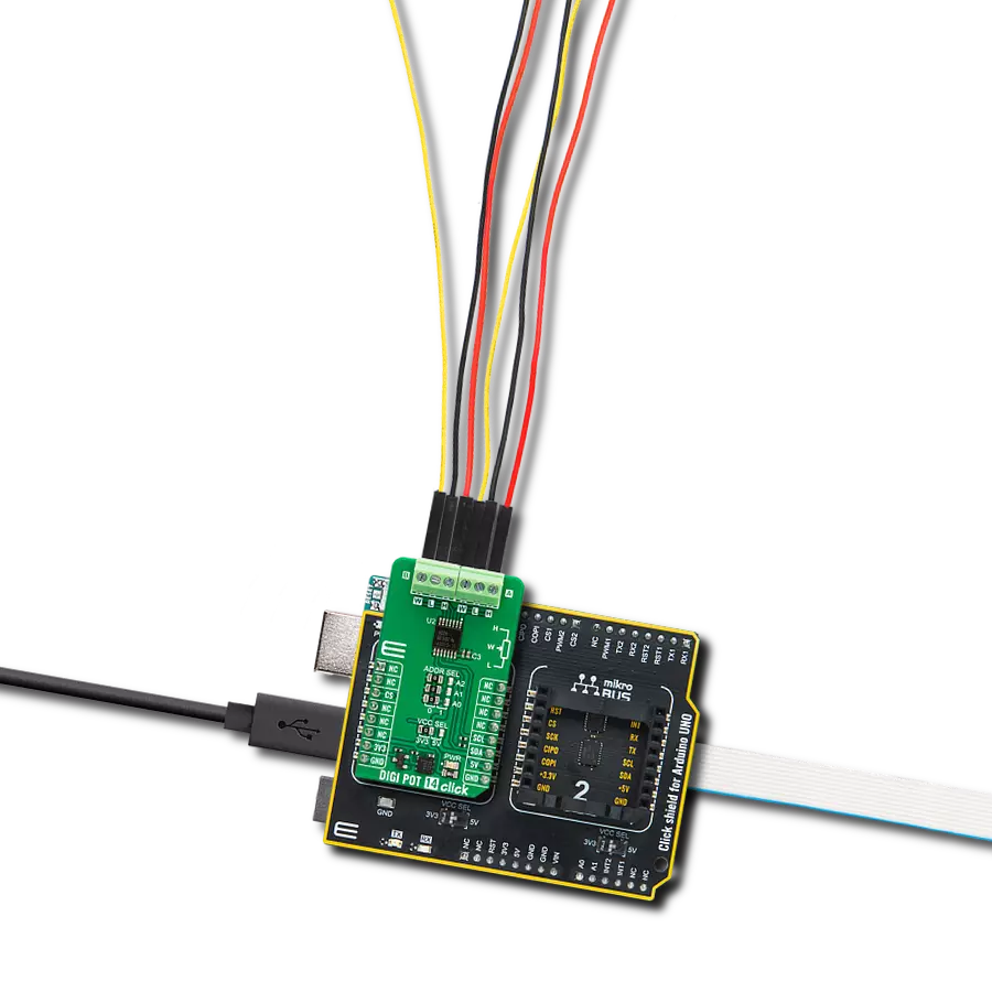
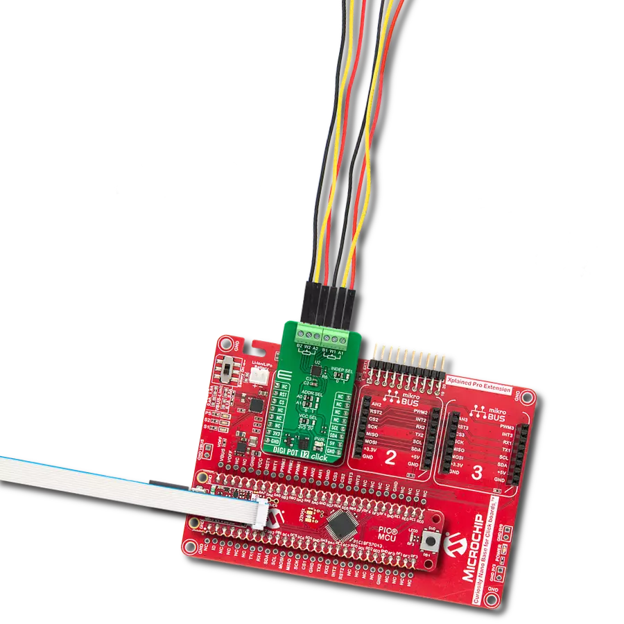
Project assembly

Start by selecting your development board and Click board™. Begin with the Curiosity Nano with PIC18F57Q43 as your development board.


Track your results in real time
Application Output
1. Application Output - In Debug mode, the 'Application Output' window enables real-time data monitoring, offering direct insight into execution results. Ensure proper data display by configuring the environment correctly using the provided tutorial.

2. UART Terminal - Use the UART Terminal to monitor data transmission via a USB to UART converter, allowing direct communication between the Click board™ and your development system. Configure the baud rate and other serial settings according to your project's requirements to ensure proper functionality. For step-by-step setup instructions, refer to the provided tutorial.

3. Plot Output - The Plot feature offers a powerful way to visualize real-time sensor data, enabling trend analysis, debugging, and comparison of multiple data points. To set it up correctly, follow the provided tutorial, which includes a step-by-step example of using the Plot feature to display Click board™ readings. To use the Plot feature in your code, use the function: plot(*insert_graph_name*, variable_name);. This is a general format, and it is up to the user to replace 'insert_graph_name' with the actual graph name and 'variable_name' with the parameter to be displayed.

Software Support
Library Description
This library contains API for DIGI POT 12 Click driver.
Key functions:
digipot12_set_resistance- DIGI POT 12 set the resistance function.digipot12_get_resistance- DIGI POT 12 get the resistance function.
Open Source
Code example
The complete application code and a ready-to-use project are available through the NECTO Studio Package Manager for direct installation in the NECTO Studio. The application code can also be found on the MIKROE GitHub account.
/*!
 * @file main.c
 * @brief DIGI POT 12 Click example
 *
 * # Description
 * This library contains API for DIGI POT 12 Click driver.
 * The demo application uses a digital potentiometer
 * to change the resistance values of both channels.
 *
 * The demo application is composed of two sections :
 *
 * ## Application Init
 * The initialization of I2C module, log UART, and additional pins.
 * After the driver init, the app executes a default configuration.
 *
 * ## Application Task
 * This example demonstrates the use of the DIGI POT 12 Click board™.
 * The demo application iterates through the entire wiper range and
 * sets the resistance of both channels in steps of approximately 1kOhm.
 * Results are being sent to the UART Terminal, where you can track their changes.
 *
 * @author Nenad Filipovic
 *
 */

#include "board.h"
#include "log.h"
#include "digipot12.h"

static digipot12_t digipot12;
static log_t logger;

void application_init ( void )
{
    log_cfg_t log_cfg;  /**< Logger config object. */
    digipot12_cfg_t digipot12_cfg;  /**< Click config object. */

    /**
     * Logger initialization.
     * Default baud rate: 115200
     * Default log level: LOG_LEVEL_DEBUG
     * @note If USB_UART_RX and USB_UART_TX
     * are defined as HAL_PIN_NC, you will
     * need to define them manually for log to work.
     * See @b LOG_MAP_USB_UART macro definition for detailed explanation.
     */
    LOG_MAP_USB_UART( log_cfg );
    log_init( &logger, &log_cfg );
    log_info( &logger, " Application Init " );

    // Click initialization.
    digipot12_cfg_setup( &digipot12_cfg );
    DIGIPOT12_MAP_MIKROBUS( digipot12_cfg, MIKROBUS_1 );
    if ( I2C_MASTER_ERROR == digipot12_init( &digipot12, &digipot12_cfg ) )
    {
        log_error( &logger, " Communication init." );
        for ( ; ; );
    }

    if ( DIGIPOT12_ERROR == digipot12_default_cfg ( &digipot12 ) )
    {
        log_error( &logger, " Default configuration." );
        for ( ; ; );
    }

    log_info( &logger, " Application Task " );
    log_printf( &logger, " ----------------------------\r\n" );
    Delay_ms ( 100 );
}

void application_task ( void )
{
    static float res_kohm;
    for ( uint8_t n_cnt = DIGIPOT12_RES_0_KOHM; n_cnt <= DIGIPOT12_RES_10_KOHM; n_cnt++ )
    {
        if ( DIGIPOT12_OK == digipot12_set_resistance( &digipot12, DIGIPOT12_WIPER_SEL_1, ( float ) n_cnt ) )
        {
            if ( DIGIPOT12_OK == digipot12_get_resistance( &digipot12, DIGIPOT12_WIPER_SEL_1, &res_kohm ) )
            {
                log_printf( &logger, " Rwb1 : %.2f kOhm\r\n", res_kohm );
                Delay_ms ( 100 );
            }
        }

        if ( DIGIPOT12_OK == digipot12_set_resistance( &digipot12, DIGIPOT12_WIPER_SEL_2, ( float ) ( DIGIPOT12_RES_10_KOHM - n_cnt ) ) )
        {
            if ( DIGIPOT12_OK == digipot12_get_resistance( &digipot12, DIGIPOT12_WIPER_SEL_2, &res_kohm ) )
            {
                log_printf( &logger, " Rwb2 : %.2f kOhm\r\n", res_kohm );
                Delay_ms ( 100 );
            }
        }
        log_printf( &logger, " ----------------------------\r\n" );
        Delay_ms ( 1000 );
        Delay_ms ( 1000 );
        Delay_ms ( 1000 );
        Delay_ms ( 1000 );
        Delay_ms ( 1000 );
    }
}

int main ( void )
{
    /* Do not remove this line or clock might not be set correctly. */
    #ifdef PREINIT_SUPPORTED
    preinit();
    #endif

    application_init( );

    for ( ; ; )
    {
        application_task( );
    }

    return 0;
}

// ------------------------------------------------------------------------ END
Additional Support
Resources
Category:Digital potentiometer