Experience navigation like never before with L86 and PIC18F57Q43
Get lost in an adventure, not in navigation

Published Feb 13, 2024
Click board™
GNSS Click
Dev. board
Curiosity Nano with PIC18F57Q43
Compiler
NECTO Studio
MCU
PIC18F57Q43
Take control of your journey and build a custom navigation system that suits all your needs
A
A
Hardware Overview
How does it work?
GNSS Click is based on the L86, a compact GNSS module from Quectel Wireless Solutions. The L86 supports the L1 band only (1575.42MHz for GPS and 1601.71MHz for GLONASS), with 33 tracking and 99 acquisition channels. Under L86's hood is the MediaTek MT3333 chipset that can achieve the perfect performance. The module is an ultra-low tracking power consumption device with a high sensitivity of -167dBm while tracking and -149dBm in acquisition mode with a reacquisition time of less than 1 second. The greater number of visible satellites increases horizontal positioning accuracy (<2.5m CEP) and decreases acquisition time (<5s TTFF with a warm start). GNSS Click supports anti-jamming and better positioning under signal conditions with onboard LNA for better sensitivity, multi-tone active interference canceller, and balloon mode for high altitudes up to 80km. The L86 can automatically predict satellite orbits from data stored in its internal flash (EASY™ technology). Also, it can adaptively adjust its ON/OFF time to balance positioning accuracy
and power consumption (AlwaysLocate™ technology). To save power consumption, GNSS Click comes with VBAT connection pads and a backup power supply selection jumper for connecting an external power supply that can supply power to the module's SRAM memory. This memory serves for storing GPS information for quick Start-Up sequences. Periodic Standby mode can periodically control the board's power on/off time to reduce average power consumption, configurable using the PMTK command. GNSS Click will enter the Periodic mode after successfully fixing the position. For communication with the host microcontroller, L86 uses the UART interface with commonly used UART RX and TX pins as its default communication protocol operating at 9600bps by default configuration to transmit and exchange data. In addition, the Click board™ features other functions accessible through mikroBUS™ signals, such as Force on (FON) and Reset (RST). A logic high state on the FON pin will force the module to
wake from Backup mode, while the RST pin provides a general reset function. In addition to the possibility of using the built-in POT antenna, this Click board™ can also use an external active antenna offered by Mikroe, thanks to the onboard u.FL connector. In addition to precise positioning, the GNSS Click has an accurate timing signal indicated via a red LED indicator marked as PPS and an AADET LED, which serves as an active antenna detection indicator. In addition to the indicator, the NMEA message will include the detection result and notification of different external active antenna statuses. This Click board™ can only be operated with a 3.3V logic voltage level. The board must perform appropriate logic voltage level conversion before using MCUs with different logic levels. However, the Click board™ comes equipped with a library containing functions and an example code that can be used as a reference for further development.

Features overview
Development board
PIC18F57Q43 Curiosity Nano evaluation kit is a cutting-edge hardware platform designed to evaluate microcontrollers within the PIC18-Q43 family. Central to its design is the inclusion of the powerful PIC18F57Q43 microcontroller (MCU), offering advanced functionalities and robust performance. Key features of this evaluation kit include a yellow user LED and a responsive
mechanical user switch, providing seamless interaction and testing. The provision for a 32.768kHz crystal footprint ensures precision timing capabilities. With an onboard debugger boasting a green power and status LED, programming and debugging become intuitive and efficient. Further enhancing its utility is the Virtual serial port (CDC) and a debug GPIO channel (DGI
GPIO), offering extensive connectivity options. Powered via USB, this kit boasts an adjustable target voltage feature facilitated by the MIC5353 LDO regulator, ensuring stable operation with an output voltage ranging from 1.8V to 5.1V, with a maximum output current of 500mA, subject to ambient temperature and voltage constraints.

Microcontroller Overview
MCU Card / MCU

Architecture
PIC
MCU Memory (KB)
128
Silicon Vendor
Microchip
Pin count
48
RAM (Bytes)
8196
You complete me!
Accessories
Curiosity Nano Base for Click boards is a versatile hardware extension platform created to streamline the integration between Curiosity Nano kits and extension boards, tailored explicitly for the mikroBUS™-standardized Click boards and Xplained Pro extension boards. This innovative base board (shield) offers seamless connectivity and expansion possibilities, simplifying experimentation and development. Key features include USB power compatibility from the Curiosity Nano kit, alongside an alternative external power input option for enhanced flexibility. The onboard Li-Ion/LiPo charger and management circuit ensure smooth operation for battery-powered applications, simplifying usage and management. Moreover, the base incorporates a fixed 3.3V PSU dedicated to target and mikroBUS™ power rails, alongside a fixed 5.0V boost converter catering to 5V power rails of mikroBUS™ sockets, providing stable power delivery for various connected devices.

Used MCU Pins
mikroBUS™ mapper
Take a closer look
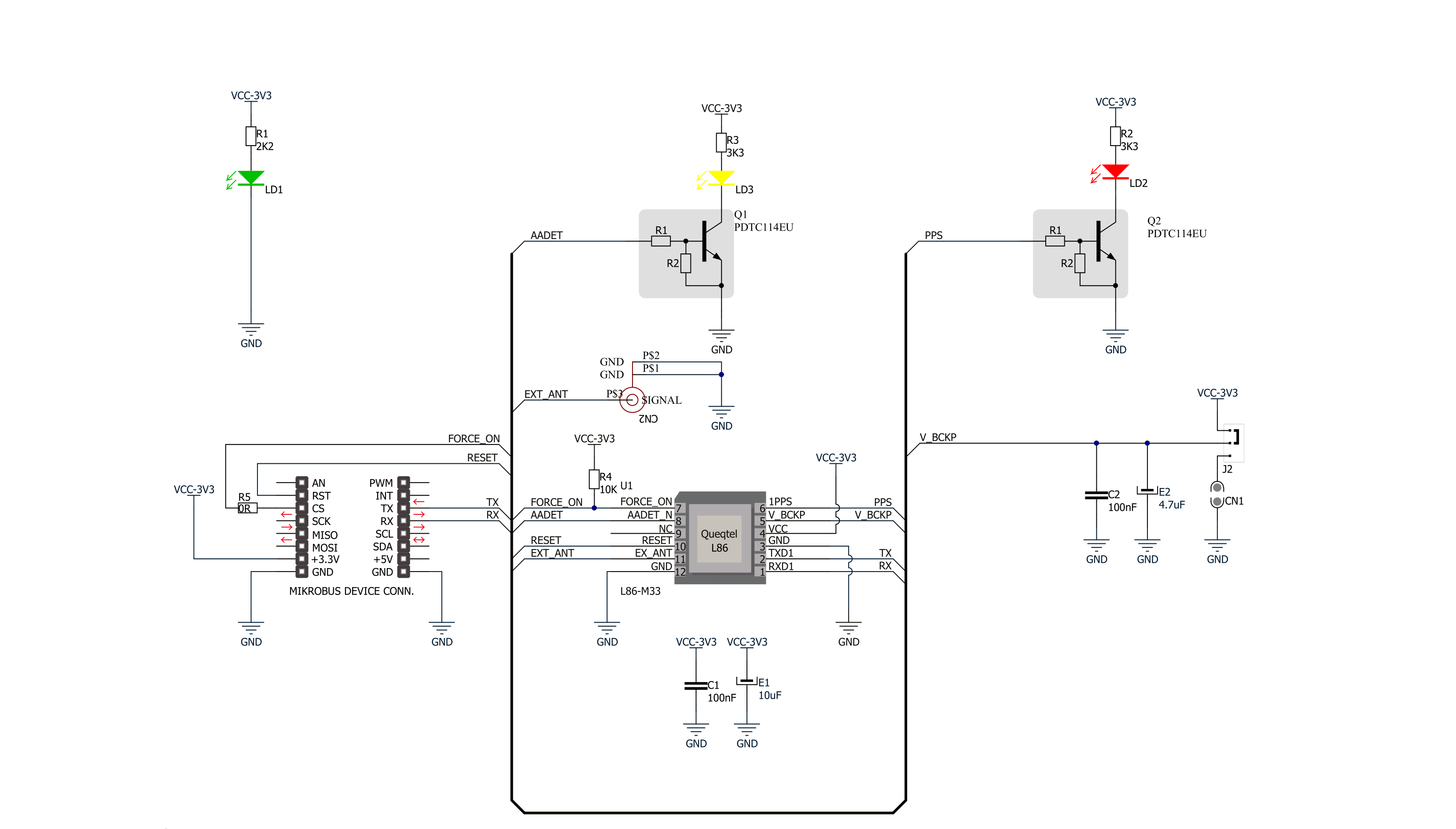
Click board™ Schematic
Step by step
Project assembly

Start by selecting your development board and Click board™. Begin with the Curiosity Nano with PIC18F57Q43 as your development board.


Software Support
Library Description
This library contains API for GNSS Click driver.
Key functions:
gnss_generic_read- This function reads a desired number of data bytes by using UART serial interfacegnss_clear_ring_buffers- This function clears UART tx and rx ring buffersgnss_parse_gpgga- This function parses the GPGGA data from the read response buffer
Open Source
Code example
The complete application code and a ready-to-use project are available through the NECTO Studio Package Manager for direct installation in the NECTO Studio. The application code can also be found on the MIKROE GitHub account.
/*!
 * @file main.c
 * @brief GNSS Click Example.
 *
 * # Description
 * This example demonstrates the use of GNSS Click by reading and displaying
 * the GPS coordinates.
 *
 * The demo application is composed of two sections :
 *
 * ## Application Init
 * Initializes the driver and logger.
 *
 * ## Application Task
 * Reads the received data, parses the GPGGA info from it, and once it receives the position fix
 * it will start displaying the coordinates on the USB UART.
 *
 * ## Additional Function
 * - static void gnss_clear_app_buf ( void )
 * - static err_t gnss_process ( gnss_t *ctx )
 * - static void gnss_parser_application ( char *rsp )
 *
 * @author Stefan Filipovic
 *
 */

#include "board.h"
#include "log.h"
#include "gnss.h"
#include "string.h"

#define PROCESS_BUFFER_SIZE 200

static gnss_t gnss;
static log_t logger;

static char app_buf[ PROCESS_BUFFER_SIZE ] = { 0 };
static int32_t app_buf_len = 0;

/**
 * @brief GNSS clearing application buffer.
 * @details This function clears memory of application buffer and reset its length.
 * @return None.
 * @note None.
 */
static void gnss_clear_app_buf ( void );

/**
 * @brief GNSS data reading function.
 * @details This function reads data from device and concatenates data to application buffer.
 * @param[in] ctx : Click context object.
 * See #gnss_t object definition for detailed explanation.
 * @return @li @c  0 - Read some data.
 *         @li @c -1 - Nothing is read.
 * See #err_t definition for detailed explanation.
 * @note None.
 */
static err_t gnss_process ( gnss_t *ctx );

/**
 * @brief GNSS parser application function.
 * @details This function parses GNSS data and logs it on the USB UART. It clears app and ring buffers
 * after successfully parsing data.
 * @param[in] ctx : Click context object.
 * See #gnss_t object definition for detailed explanation.
 * @param[in] rsp Response buffer.
 * @return None.
 * @note None.
 */
static void gnss_parser_application ( gnss_t *ctx, char *rsp );

void application_init ( void )
{
    log_cfg_t log_cfg;  /**< Logger config object. */
    gnss_cfg_t gnss_cfg;  /**< Click config object. */

    /**
     * Logger initialization.
     * Default baud rate: 115200
     * Default log level: LOG_LEVEL_DEBUG
     * @note If USB_UART_RX and USB_UART_TX
     * are defined as HAL_PIN_NC, you will
     * need to define them manually for log to work.
     * See @b LOG_MAP_USB_UART macro definition for detailed explanation.
     */
    LOG_MAP_USB_UART( log_cfg );
    log_init( &logger, &log_cfg );
    log_info( &logger, " Application Init " );

    // Click initialization.
    gnss_cfg_setup( &gnss_cfg );
    GNSS_MAP_MIKROBUS( gnss_cfg, MIKROBUS_1 );
    if ( UART_ERROR == gnss_init( &gnss, &gnss_cfg ) )
    {
        log_error( &logger, " Communication init." );
        for ( ; ; );
    }
    log_info( &logger, " Application Task " );
}

void application_task ( void )
{
    if ( GNSS_OK == gnss_process( &gnss ) )
    {
        if ( PROCESS_BUFFER_SIZE == app_buf_len )
        {
            gnss_parser_application( &gnss, app_buf );
        }
    }
}

int main ( void )
{
    /* Do not remove this line or clock might not be set correctly. */
    #ifdef PREINIT_SUPPORTED
    preinit();
    #endif

    application_init( );

    for ( ; ; )
    {
        application_task( );
    }

    return 0;
}

static void gnss_clear_app_buf ( void )
{
    memset( app_buf, 0, app_buf_len );
    app_buf_len = 0;
}

static err_t gnss_process ( gnss_t *ctx )
{
    char rx_buf[ PROCESS_BUFFER_SIZE ] = { 0 };
    int32_t rx_size = 0;
    rx_size = gnss_generic_read( ctx, rx_buf, PROCESS_BUFFER_SIZE );
    if ( rx_size > 0 )
    {
        int32_t buf_cnt = app_buf_len;
        if ( ( ( app_buf_len + rx_size ) > PROCESS_BUFFER_SIZE ) && ( app_buf_len > 0 ) )
        {
            buf_cnt = PROCESS_BUFFER_SIZE - ( ( app_buf_len + rx_size ) - PROCESS_BUFFER_SIZE );
            memmove ( app_buf, &app_buf[ PROCESS_BUFFER_SIZE - buf_cnt ], buf_cnt );
        }
        for ( int32_t rx_cnt = 0; rx_cnt < rx_size; rx_cnt++ )
        {
            if ( rx_buf[ rx_cnt ] )
            {
                app_buf[ buf_cnt++ ] = rx_buf[ rx_cnt ];
                if ( app_buf_len < PROCESS_BUFFER_SIZE )
                {
                    app_buf_len++;
                }
            }
        }
        return GNSS_OK;
    }
    return GNSS_ERROR;
}

static void gnss_parser_application ( gnss_t *ctx, char *rsp )
{
    char element_buf[ 100 ] = { 0 };
    if ( GNSS_OK == gnss_parse_gpgga( rsp, GNSS_GPGGA_LATITUDE, element_buf ) )
    {
        static uint8_t wait_for_fix_cnt = 0;
        if ( strlen( element_buf ) > 0 )
        {
            log_printf( &logger, "\r\n Latitude: %.2s degrees, %s minutes \r\n", element_buf, &element_buf[ 2 ] );
            gnss_parse_gpgga( rsp, GNSS_GPGGA_LONGITUDE, element_buf );
            log_printf( &logger, " Longitude: %.3s degrees, %s minutes \r\n", element_buf, &element_buf[ 3 ] );
            memset( element_buf, 0, sizeof( element_buf ) );
            gnss_parse_gpgga( rsp, GNSS_GPGGA_ALTITUDE, element_buf );
            log_printf( &logger, " Altitude: %s m \r\n", element_buf );
            wait_for_fix_cnt = 0;
        }
        else
        {
            if ( wait_for_fix_cnt % 5 == 0 )
            {
                log_printf( &logger, " Waiting for the position fix...\r\n\n" );
                wait_for_fix_cnt = 0;
            }
            wait_for_fix_cnt++;
        }
        gnss_clear_ring_buffers( ctx );
        gnss_clear_app_buf( );
    }
}

// ------------------------------------------------------------------------ END
Additional Support
Resources
Category:GPS/GNSS


