Ensure uniform brightness and unmatched control in your lighting projects using MP3309C and PIC18F57Q43
Lighting excellence starts here
Published Feb 13, 2024
Click board™
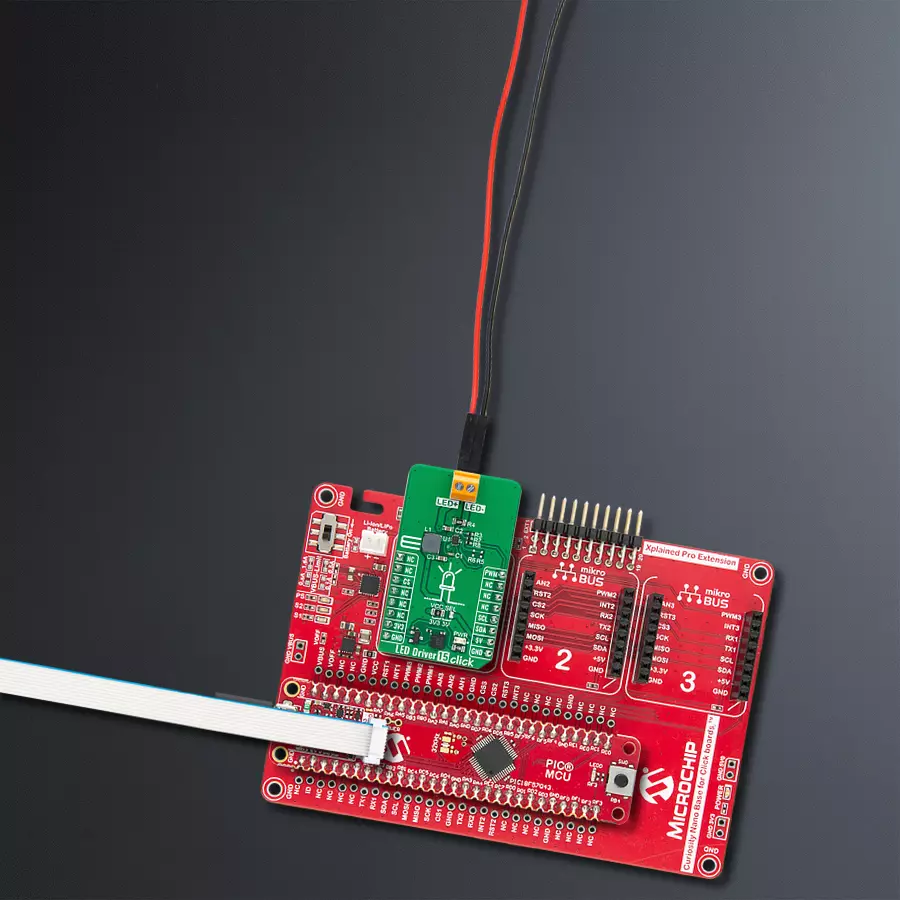
LED Driver 15 Click
Dev. board
Curiosity Nano with PIC18F57Q43
Compiler
NECTO Studio
MCU
PIC18F57Q43
Our LED driver solution harmoniously powers up to 8 white LEDs in series, offering a brilliant and energy-efficient lighting experience for various applications
A
A
Hardware Overview
How does it work?
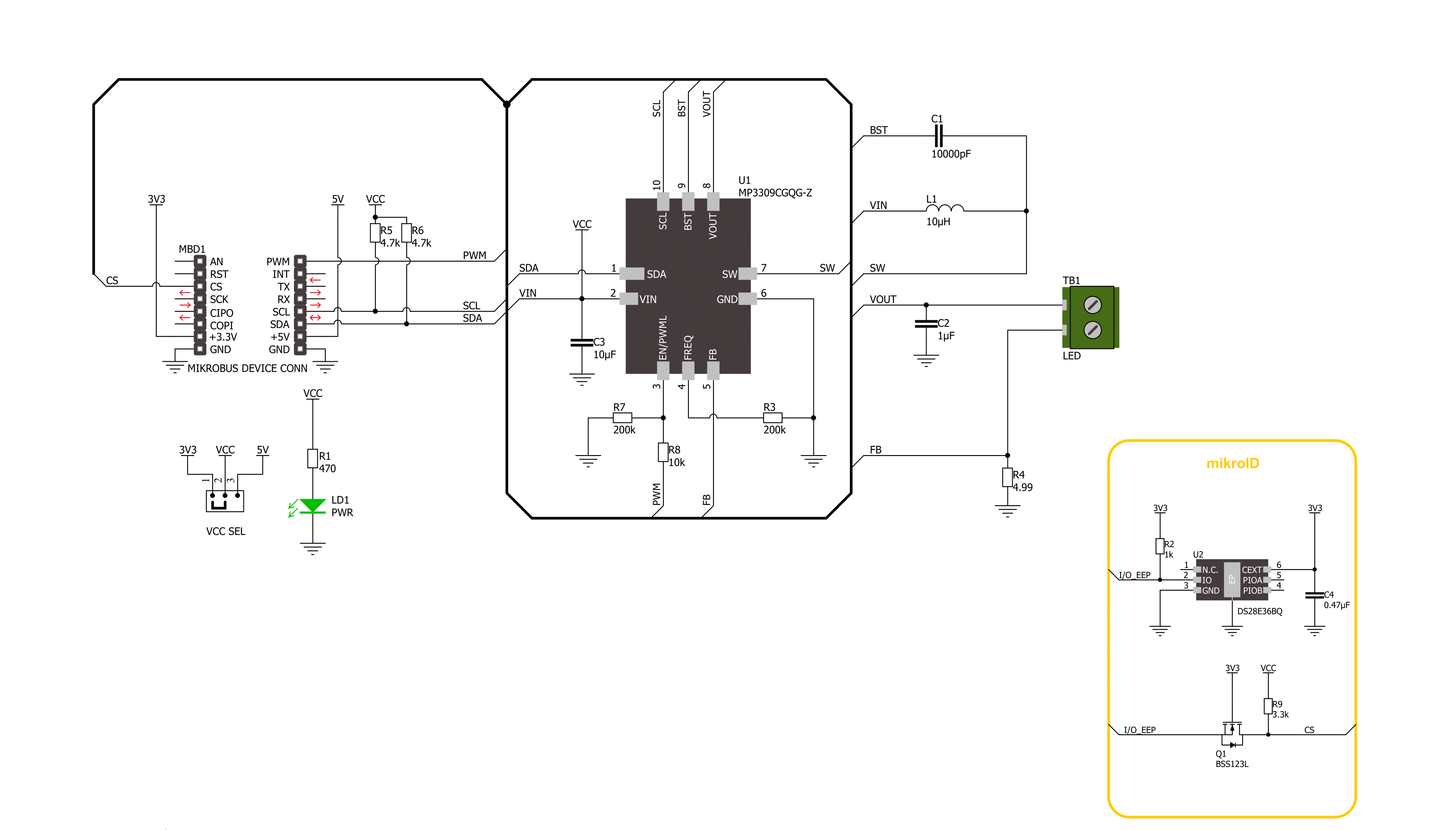
LED Driver 15 Click is based on the MP3309C, a white LED step-up converter from Monolithic Power Systems that uses peak current mode to regulate the current through the LED string using an external low-side resistor. The MP3309C offers high efficiency and features a programmable switching frequency to optimize efficiency. It delivers up to 40mA of LED current supporting up to 8 white LEDs in series connected to the LED terminal. The MP3309C also has integrated protection circuitry to guard against thermal overstress and electrical damage, featuring LED
open protection, cycle-by-cycle current limit protection, under-voltage protection (UVP), and thermal shutdown protection. The MP3309C provides two dimming methods, PWM and analog dimming mode. It uses a PWM signal from the mikroBUS™ socket for PWM dimming. When the PWM signal is in a low logic state, the MP3309C stops switching and resumes Normal operation when the PWM signal is in a high logic state. Using a 100Hz to 2kHz PWM dimming frequency for most dimming ratio requests is recommended. The MP3309C set the LED current amplitude for
analog dimming through the I2C interface. LED Driver 15 Click communicates with MCU using the standard I2C 2-Wire interface that supports Standard-Mode (100 kHz) and Fast-Mode (400 kHz) operation. This Click board™ can operate with either 3.3V or 5V logic voltage levels selected via the VCC SEL jumper. This way, both 3.3V and 5V capable MCUs can use the communication lines properly. Also, this Click board™ comes equipped with a library containing easy-to-use functions and an example code that can be used as a reference for further development.


Features overview
Development board
PIC18F57Q43 Curiosity Nano evaluation kit is a cutting-edge hardware platform designed to evaluate microcontrollers within the PIC18-Q43 family. Central to its design is the inclusion of the powerful PIC18F57Q43 microcontroller (MCU), offering advanced functionalities and robust performance. Key features of this evaluation kit include a yellow user LED and a responsive
mechanical user switch, providing seamless interaction and testing. The provision for a 32.768kHz crystal footprint ensures precision timing capabilities. With an onboard debugger boasting a green power and status LED, programming and debugging become intuitive and efficient. Further enhancing its utility is the Virtual serial port (CDC) and a debug GPIO channel (DGI
GPIO), offering extensive connectivity options. Powered via USB, this kit boasts an adjustable target voltage feature facilitated by the MIC5353 LDO regulator, ensuring stable operation with an output voltage ranging from 1.8V to 5.1V, with a maximum output current of 500mA, subject to ambient temperature and voltage constraints.

Microcontroller Overview
MCU Card / MCU

Architecture
PIC
MCU Memory (KB)
128
Silicon Vendor
Microchip
Pin count
48
RAM (Bytes)
8196
You complete me!
Accessories
Curiosity Nano Base for Click boards is a versatile hardware extension platform created to streamline the integration between Curiosity Nano kits and extension boards, tailored explicitly for the mikroBUS™-standardized Click boards and Xplained Pro extension boards. This innovative base board (shield) offers seamless connectivity and expansion possibilities, simplifying experimentation and development. Key features include USB power compatibility from the Curiosity Nano kit, alongside an alternative external power input option for enhanced flexibility. The onboard Li-Ion/LiPo charger and management circuit ensure smooth operation for battery-powered applications, simplifying usage and management. Moreover, the base incorporates a fixed 3.3V PSU dedicated to target and mikroBUS™ power rails, alongside a fixed 5.0V boost converter catering to 5V power rails of mikroBUS™ sockets, providing stable power delivery for various connected devices.

Used MCU Pins
mikroBUS™ mapper
Take a closer look
Click board™ Schematic
Step by step
Project assembly

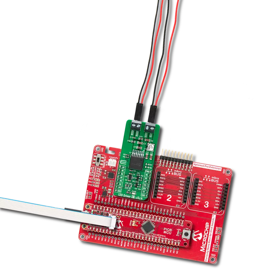
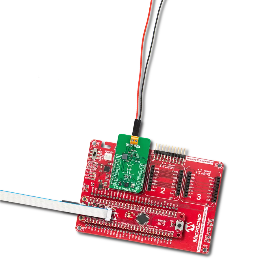
Start by selecting your development board and Click board™. Begin with the Curiosity Nano with PIC18F57Q43 as your development board.


Track your results in real time
Application Output
1. Application Output - In Debug mode, the 'Application Output' window enables real-time data monitoring, offering direct insight into execution results. Ensure proper data display by configuring the environment correctly using the provided tutorial.

2. UART Terminal - Use the UART Terminal to monitor data transmission via a USB to UART converter, allowing direct communication between the Click board™ and your development system. Configure the baud rate and other serial settings according to your project's requirements to ensure proper functionality. For step-by-step setup instructions, refer to the provided tutorial.

3. Plot Output - The Plot feature offers a powerful way to visualize real-time sensor data, enabling trend analysis, debugging, and comparison of multiple data points. To set it up correctly, follow the provided tutorial, which includes a step-by-step example of using the Plot feature to display Click board™ readings. To use the Plot feature in your code, use the function: plot(*insert_graph_name*, variable_name);. This is a general format, and it is up to the user to replace 'insert_graph_name' with the actual graph name and 'variable_name' with the parameter to be displayed.

Software Support
Library Description
This library contains API for LED Driver 15 Click driver.
Key functions:
leddriver15_set_i2c_dimming- This function sets the LEDs dimming level in I2C modeleddriver15_enable_device- This function enables the device by setting the EN pin to high logic stateleddriver15_disable_device- This function disables the device by setting the EN pin to low logic state.
Open Source
Code example
The complete application code and a ready-to-use project are available through the NECTO Studio Package Manager for direct installation in the NECTO Studio. The application code can also be found on the MIKROE GitHub account.
/*!
 * @file main.c
 * @brief LED Driver 15 Click example
 *
 * # Description
 * This example demonstrates the use of LED Driver 15 Click board by changing
 * the LEDs dimming level.
 *
 * The demo application is composed of two sections :
 *
 * ## Application Init
 * Initializes the driver and performs the Click default configuration.
 *
 * ## Application Task
 * Changes the LEDs dimming level in I2C mode every 500ms. The dimming level will be
 * displayed on the USB UART.
 *
 * @note
 * It is recommended to connect 8 LEDs in series (40mA) to the output connector.
 *
 * @author Stefan Filipovic
 *
 */

#include "board.h"
#include "log.h"
#include "leddriver15.h"

static leddriver15_t leddriver15;
static log_t logger;

void application_init ( void )
{
    log_cfg_t log_cfg;  /**< Logger config object. */
    leddriver15_cfg_t leddriver15_cfg;  /**< Click config object. */

    /**
     * Logger initialization.
     * Default baud rate: 115200
     * Default log level: LOG_LEVEL_DEBUG
     * @note If USB_UART_RX and USB_UART_TX
     * are defined as HAL_PIN_NC, you will
     * need to define them manually for log to work.
     * See @b LOG_MAP_USB_UART macro definition for detailed explanation.
     */
    LOG_MAP_USB_UART( log_cfg );
    log_init( &logger, &log_cfg );
    log_info( &logger, " Application Init " );

    // Click initialization.
    leddriver15_cfg_setup( &leddriver15_cfg );
    LEDDRIVER15_MAP_MIKROBUS( leddriver15_cfg, MIKROBUS_1 );
    if ( LEDDRIVER15_OK != leddriver15_init( &leddriver15, &leddriver15_cfg ) )
    {
        log_error( &logger, " Communication init." );
        for ( ; ; );
    }

    if ( LEDDRIVER15_OK != leddriver15_default_cfg ( &leddriver15 ) )
    {
        log_error( &logger, " Default configuration." );
        for ( ; ; );
    }

    log_info( &logger, " Application Task " );
}

void application_task ( void )
{
    static uint8_t dimming = LEDDRIVER15_I2C_DIMMING_MIN;
    if ( LEDDRIVER15_OK == leddriver15_set_i2c_dimming ( &leddriver15, dimming ) )
    {
        log_printf( &logger, " Dimming level: %u\r\n\n", ( uint16_t ) dimming );
    }
    if ( ++dimming > LEDDRIVER15_I2C_DIMMING_MAX )
    {
        dimming = LEDDRIVER15_I2C_DIMMING_MIN;
    }
    Delay_ms ( 500 );
}

int main ( void )
{
    /* Do not remove this line or clock might not be set correctly. */
    #ifdef PREINIT_SUPPORTED
    preinit();
    #endif

    application_init( );

    for ( ; ; )
    {
        application_task( );
    }

    return 0;
}

// ------------------------------------------------------------------------ END
Additional Support
Resources
Category:LED Drivers