Open the door to immersive hands-free interfaces that respond to your presence using RPR-0521RS and PIC18F57Q43
Making life easier, one step at a time

Published Feb 13, 2024
Click board™
Proximity 11 Click
Dev. board
Curiosity Nano with PIC18F57Q43
Compiler
NECTO Studio
MCU
PIC18F57Q43
Proximity detection is no longer science fiction; it's a reality that's here to redefine how we connect with the world
A
A
Hardware Overview
How does it work?
Proximity 11 Click is based on the RPR-0521RS, a digital ambient and proximity sensor from ROHM Semiconductor. It is an accurate and reliable proximity and ambient light sensor, aimed towards the power saving in applications that use TFT or LCD panels. By offering a huge dynamic range, the RPR-0521RS sensor allows to be placed behind a dark glass or a semi-transparent screen bezel, but also to be exposed to a bright sunlight. A proprietary design of the integrated constant-current LED driver enables plug and play proximity detection from 1, up to 100mm, eliminating the need for a calibration procedure. By integrating micro-optics elements within the casing, RPR-0521RS greatly simplifies the application design. Proximity of an object is detected using an IR LED, which emits pulses of light towards the object. The amount of the reflected IR light is measured by an integrated IR photodiode. During LED pulse duration time, the amount of the reflected IR light is measured and
integrated. The background IR light is also measured and integrated, during LED OFF state. It is then subtracted from the final result, allowing for an accurate measurement with the reduced amount of the background IR noise. After it has been scaled to a 16-bit value, the final result is available on the output registers, in the LOW/HIGH byte format. Commonly, photosensitive elements are most sensitive to IR light. A human eye does cannot detect IR light. Therefore, the PD element has to filter out IR light so that only the visible part of the light is allowed through. The channel0 is equipped with such PD, making it usable for the ALS sensing. During the ALS measurement, both channels are measured. The datasheet of the RPR-0521RS offers a conversion formula that can be used to obtain results in physical units (lx). These formulas also take the IR measurement from the channel 1 into the consideration, completely reducing its influence on the final result. By adjusting the integration time (also known
as oversampling), the flickering effect of a fluorescent light can be completely eliminated. The extensive interrupt engine allows an optimized firmware to be written. Four registers are used to specify the low and the high threshold for the ALS and proximity measurements. Whenever these thresholds are exceeded, an interrupt status bit will be set in the respective register. The user has the ability to assign an external pin to an interrupt, so the MCU can be alerted whenever an interrupt event occurs. The interrupt is generated whenever the threshold value is exceeded for a programmed number of times (interrupt persistence). This is useful to prevent false and erratic interrupt reporting. The Click board™ is designed to work with 3.3V only. When using it with MCUs that use 5V levels for their communication, a proper level translation circuit should be used.


Features overview
Development board
PIC18F57Q43 Curiosity Nano evaluation kit is a cutting-edge hardware platform designed to evaluate microcontrollers within the PIC18-Q43 family. Central to its design is the inclusion of the powerful PIC18F57Q43 microcontroller (MCU), offering advanced functionalities and robust performance. Key features of this evaluation kit include a yellow user LED and a responsive
mechanical user switch, providing seamless interaction and testing. The provision for a 32.768kHz crystal footprint ensures precision timing capabilities. With an onboard debugger boasting a green power and status LED, programming and debugging become intuitive and efficient. Further enhancing its utility is the Virtual serial port (CDC) and a debug GPIO channel (DGI
GPIO), offering extensive connectivity options. Powered via USB, this kit boasts an adjustable target voltage feature facilitated by the MIC5353 LDO regulator, ensuring stable operation with an output voltage ranging from 1.8V to 5.1V, with a maximum output current of 500mA, subject to ambient temperature and voltage constraints.

Microcontroller Overview
MCU Card / MCU

Architecture
PIC
MCU Memory (KB)
128
Silicon Vendor
Microchip
Pin count
48
RAM (Bytes)
8196
You complete me!
Accessories
Curiosity Nano Base for Click boards is a versatile hardware extension platform created to streamline the integration between Curiosity Nano kits and extension boards, tailored explicitly for the mikroBUS™-standardized Click boards and Xplained Pro extension boards. This innovative base board (shield) offers seamless connectivity and expansion possibilities, simplifying experimentation and development. Key features include USB power compatibility from the Curiosity Nano kit, alongside an alternative external power input option for enhanced flexibility. The onboard Li-Ion/LiPo charger and management circuit ensure smooth operation for battery-powered applications, simplifying usage and management. Moreover, the base incorporates a fixed 3.3V PSU dedicated to target and mikroBUS™ power rails, alongside a fixed 5.0V boost converter catering to 5V power rails of mikroBUS™ sockets, providing stable power delivery for various connected devices.

Used MCU Pins
mikroBUS™ mapper
Take a closer look
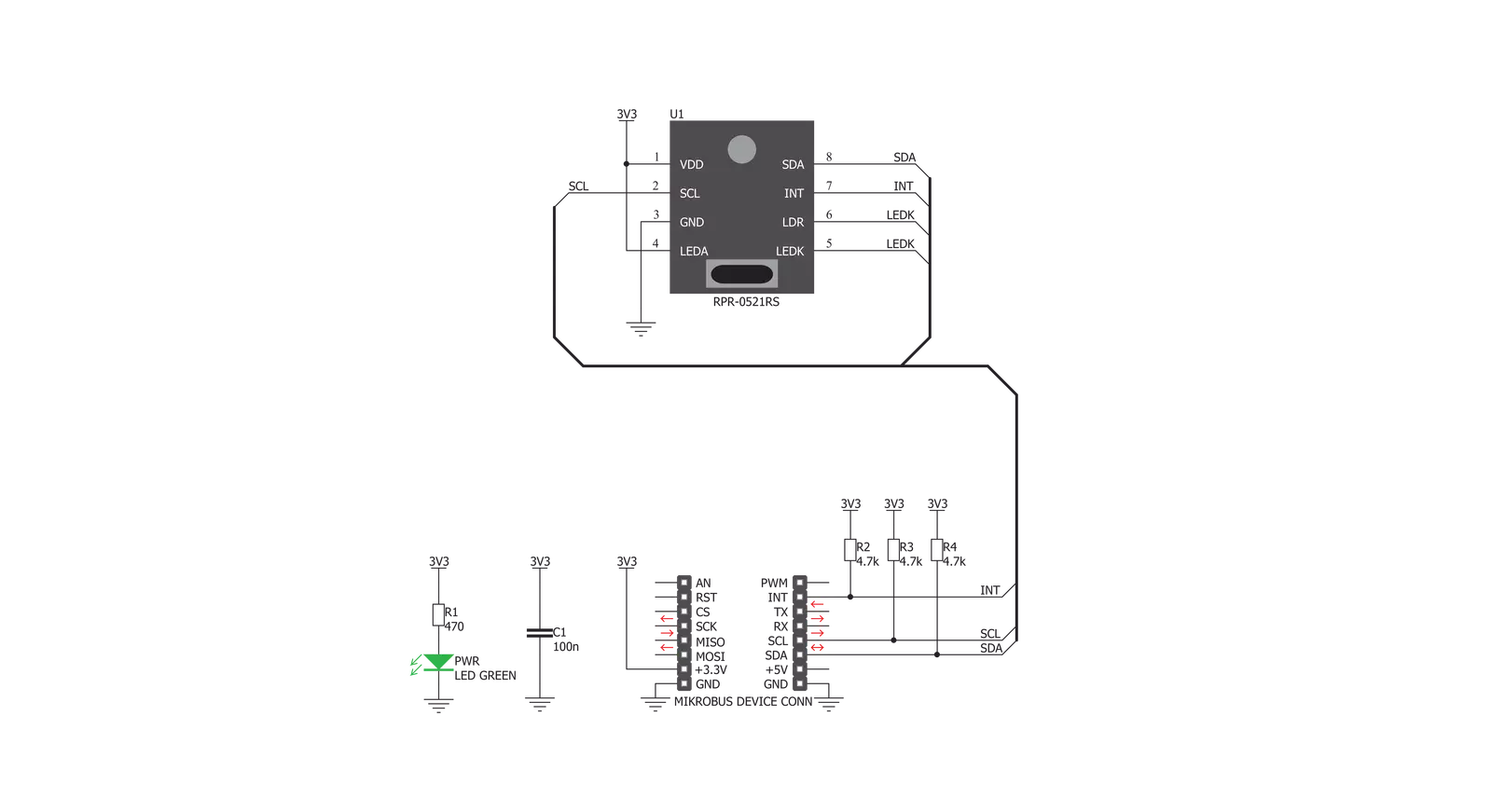
Click board™ Schematic
Step by step
Project assembly

Start by selecting your development board and Click board™. Begin with the Curiosity Nano with PIC18F57Q43 as your development board.


Software Support
Library Description
This library contains API for Proximity 11 Click driver.
Key functions:
proximity11_get- This function reads proximity values from the desired registers.proximity11_update- This function updates data used to calculate Lux. This function should be called if changing als measurement time and als gain.proximity11_set_als_threshold_high- This function sets High ALS threshold value.
Open Source
Code example
The complete application code and a ready-to-use project are available through the NECTO Studio Package Manager for direct installation in the NECTO Studio. The application code can also be found on the MIKROE GitHub account.
/*!
 * \file
 * \brief Proximity11 Click example
 *
 * # Description
 * This appication enables usage of the proximity and ambient light sensors
 *
 * The demo application is composed of two sections :
 *
 * ## Application Init
 * Initializes I2C driver and performs device initialization
 *
 * ## Application Task
 * Gets ALS and PS values and logs those values
 *
 * \author MikroE Team
 *
 */
// ------------------------------------------------------------------- INCLUDES

#include "board.h"
#include "log.h"
#include "proximity11.h"

// ------------------------------------------------------------------ VARIABLES

static proximity11_t proximity11;
static log_t logger;

// ------------------------------------------------------ APPLICATION FUNCTIONS

void application_init ( void )
{
    log_cfg_t log_cfg;
    proximity11_cfg_t cfg;
    uint8_t init_status;

    /**
     * Logger initialization.
     * Default baud rate: 115200
     * Default log level: LOG_LEVEL_DEBUG
     * @note If USB_UART_RX and USB_UART_TX
     * are defined as HAL_PIN_NC, you will
     * need to define them manually for log to work.
     * See @b LOG_MAP_USB_UART macro definition for detailed explanation.
     */
    LOG_MAP_USB_UART( log_cfg );
    log_init( &logger, &log_cfg );
    log_info( &logger, "---- Application Init ----" );

    //  Click initialization.

    proximity11_cfg_setup( &cfg );
    PROXIMITY11_MAP_MIKROBUS( cfg, MIKROBUS_1 );
    proximity11_init( &proximity11, &cfg );

    Delay_ms ( 500 );

    init_status = proximity11_default_cfg( &proximity11 );

    if ( init_status == 1 )
    {
        log_printf( &logger, "> app init fail\r\n" );
		while( 1 );
    }
    else if ( init_status == 0 )
    {
        log_printf( &logger, "> app init done\r\n" );
    }
}

void application_task ( void )
{
    //  Task implementation

    uint16_t ps_value;
    float als_value;

    proximity11_get_ps_als_values( &proximity11, &ps_value, &als_value );

    log_printf( &logger, "PS  : %u [count]\r\n", ps_value );
    log_printf( &logger, "ALS : %.2f [Lx]\r\n\r\n", als_value );

    Delay_ms ( 500 );

}

int main ( void )
{
    /* Do not remove this line or clock might not be set correctly. */
    #ifdef PREINIT_SUPPORTED
    preinit();
    #endif

    application_init( );

    for ( ; ; )
    {
        application_task( );
    }

    return 0;
}


// ------------------------------------------------------------------------ END
Additional Support
Resources
Category:Proximity


