Explore the endless potential of proximity detection with TMD3719 and PIC18F57Q43
Proximity sensing: Creating smarter and safer environments

Published Feb 13, 2024
Click board™
Proximity 12 Click
Dev. board
Curiosity Nano with PIC18F57Q43
Compiler
NECTO Studio
MCU
PIC18F57Q43
With proximity detection, we're unlocking the doors to a world where automation and personalization combine to enhance every moment
A
A
Hardware Overview
How does it work?
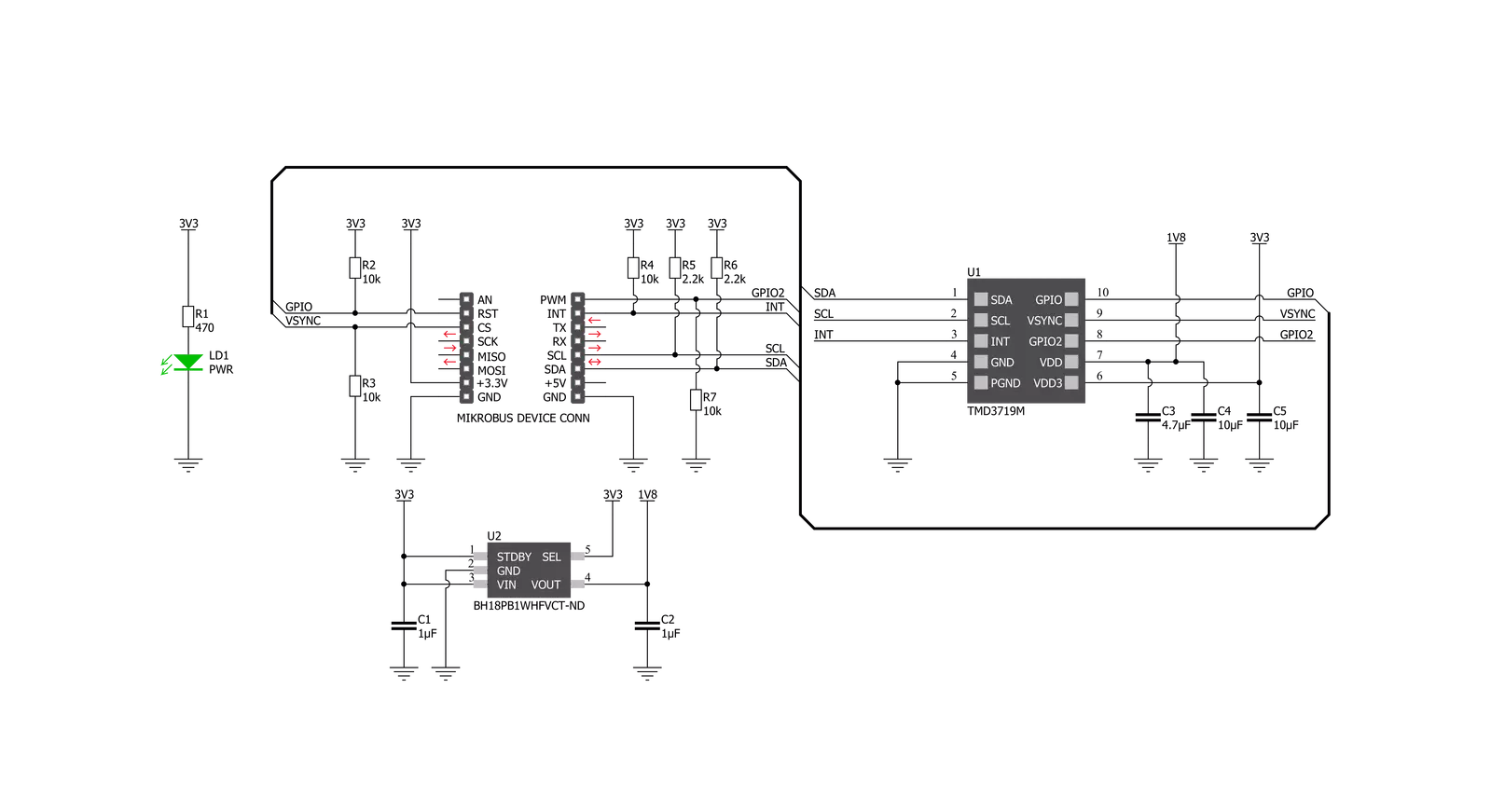
Proximity 12 Click is based on the TMD3719, an optical sensor that integrates ambient light sensing, proximity detection, and flicker detection sensing from ams OSRAM. The ambient light and color sensing function provide six concurrent ambient light sensing channels: Red, Green, Blue, Clear, Leakage, and Wideband, which accurately measure ambient light and calculate illuminance, chromaticity, and color temperature. The TMD3719 also integrates direct detection of ambient light flicker for four selectable frequency bins, executed parallel with ambient light and color sensing. The proximity function synchronizes IR emission and detection to sense nearby objects. This function features self-maximizing dynamic range, ambient light subtraction, and advanced cross-talk cancelation. The proximity engine recognizes
detect/release events and produces a configurable interrupt, routed to the INT pin of the mikroBUS™ socket, whenever the proximity result crosses upper or lower threshold settings. Proximity 12 Click communicates with MCU using the standard I2C 2-Wire interface with a maximum clock frequency of up to 400kHz. In addition to I2C communication, several GPIO pins connected to the mikroBUS™ socket pins are also used. The SYN pin, routed to the CS pin of the mikroBUS™ socket, is used to synchronize data and allows the start of the classic ambient light, proximity sensing, and flicker detection with every new SYN signal instead of immediately. It also has two pins labeled GP1 and GP2, routed on the RST and PWM pins of the mikroBUS™ socket, used as general-purpose pins, more precisely, GP1 as open-drain
general-purpose input/output and GP2 only as an input pin. The TMD3719 requires a supply voltage of 1.8V to work correctly. Therefore, a small regulating LDO, the BH18PB1WHFV from Rohm Semiconductor, provides a 1.8V out of 3.3V mikroBUS™ rail. The LDO cuts power consumption by lowering its current consumption to approximately 2μA when the application operates in the Standby state. This Click board™ can be operated only with a 3.3V logic voltage level. The board must perform appropriate logic voltage level conversion before using MCUs with different logic levels. Also, it comes equipped with a library containing functions and an example code that can be used as a reference for further development.


Features overview
Development board
PIC18F57Q43 Curiosity Nano evaluation kit is a cutting-edge hardware platform designed to evaluate microcontrollers within the PIC18-Q43 family. Central to its design is the inclusion of the powerful PIC18F57Q43 microcontroller (MCU), offering advanced functionalities and robust performance. Key features of this evaluation kit include a yellow user LED and a responsive
mechanical user switch, providing seamless interaction and testing. The provision for a 32.768kHz crystal footprint ensures precision timing capabilities. With an onboard debugger boasting a green power and status LED, programming and debugging become intuitive and efficient. Further enhancing its utility is the Virtual serial port (CDC) and a debug GPIO channel (DGI
GPIO), offering extensive connectivity options. Powered via USB, this kit boasts an adjustable target voltage feature facilitated by the MIC5353 LDO regulator, ensuring stable operation with an output voltage ranging from 1.8V to 5.1V, with a maximum output current of 500mA, subject to ambient temperature and voltage constraints.

Microcontroller Overview
MCU Card / MCU

Architecture
PIC
MCU Memory (KB)
128
Silicon Vendor
Microchip
Pin count
48
RAM (Bytes)
8196
You complete me!
Accessories
Curiosity Nano Base for Click boards is a versatile hardware extension platform created to streamline the integration between Curiosity Nano kits and extension boards, tailored explicitly for the mikroBUS™-standardized Click boards and Xplained Pro extension boards. This innovative base board (shield) offers seamless connectivity and expansion possibilities, simplifying experimentation and development. Key features include USB power compatibility from the Curiosity Nano kit, alongside an alternative external power input option for enhanced flexibility. The onboard Li-Ion/LiPo charger and management circuit ensure smooth operation for battery-powered applications, simplifying usage and management. Moreover, the base incorporates a fixed 3.3V PSU dedicated to target and mikroBUS™ power rails, alongside a fixed 5.0V boost converter catering to 5V power rails of mikroBUS™ sockets, providing stable power delivery for various connected devices.

Used MCU Pins
mikroBUS™ mapper
Take a closer look
Click board™ Schematic
Step by step
Project assembly

Start by selecting your development board and Click board™. Begin with the Curiosity Nano with PIC18F57Q43 as your development board.


Software Support
Library Description
This library contains API for Proximity 12 Click driver.
Key functions:
proximity12_read_proximity- This function reads the raw proximity value measured by the click board.proximity12_read_als- This function reads all als data measured by the click board.proximity12_set_led_isink- This function sets the LEDs sink scaler and current values.
Open Source
Code example
The complete application code and a ready-to-use project are available through the NECTO Studio Package Manager for direct installation in the NECTO Studio. The application code can also be found on the MIKROE GitHub account.
/*!
 * @file main.c
 * @brief Proximity12 Click example
 *
 * # Description
 * This function demonstrates the use of Proximity 12 Click board.
 *
 * The demo application is composed of two sections :
 *
 * ## Application Init
 * Initializes the driver and performs the Click default configuration.
 *
 * ## Application Task
 * Reads the proximity and ALS values and displays the results on the USB UART
 * approximately every 100ms.
 *
 * @author Stefan Filipovic
 *
 */

#include "board.h"
#include "log.h"
#include "proximity12.h"

static proximity12_t proximity12;
static log_t logger;

void application_init ( void )
{
    log_cfg_t log_cfg;                  /**< Logger config object. */
    proximity12_cfg_t proximity12_cfg;  /**< Click config object. */

    /**
     * Logger initialization.
     * Default baud rate: 115200
     * Default log level: LOG_LEVEL_DEBUG
     * @note If USB_UART_RX and USB_UART_TX
     * are defined as HAL_PIN_NC, you will
     * need to define them manually for log to work.
     * See @b LOG_MAP_USB_UART macro definition for detailed explanation.
     */
    LOG_MAP_USB_UART( log_cfg );
    log_init( &logger, &log_cfg );
    Delay_ms ( 100 );
    log_info( &logger, " Application Init " );

    // Click initialization.
    proximity12_cfg_setup( &proximity12_cfg );
    PROXIMITY12_MAP_MIKROBUS( proximity12_cfg, MIKROBUS_1 );
    err_t init_flag = proximity12_init( &proximity12, &proximity12_cfg );
    if ( I2C_MASTER_ERROR == init_flag )
    {
        log_error( &logger, " Application Init Error. " );
        log_info( &logger, " Please, run program again... " );

        for ( ; ; );
    }
    Delay_ms ( 100 );

    init_flag = proximity12_default_cfg ( &proximity12 );
    if ( PROXIMITY12_ERROR == init_flag )
    {
        log_error( &logger, " Default Cfg Error. " );
        log_info( &logger, " Please, run program again... " );

        for ( ; ; );
    }
    log_info( &logger, " Application Task " );
}

void application_task ( void )
{
    uint16_t prox_data = 0;
    proximity12_als_data_t als;
    err_t error_flag = proximity12_read_proximity ( &proximity12, &prox_data );
    error_flag |= proximity12_read_als ( &proximity12, &als );

    if ( PROXIMITY12_OK == error_flag )
    {
        log_printf( &logger, " - Proximity data -\r\n" );
        log_printf( &logger, " Proximity: %u\r\n", prox_data );
        log_printf( &logger, " - ALS data -\r\n" );
        log_printf( &logger, " Clear: %lu - Red: %lu - Green: %lu - Blue: %lu\r\n", als.clear,
                                                                                    als.red,
                                                                                    als.green,
                                                                                    als.blue );

        log_printf( &logger, " Leakage: %lu - Wideband: %lu - IR1: %lu - IR2: %lu\r\n\r\n", als.leakage,
                                                                                            als.wideband,
                                                                                            als.ir1,
                                                                                            als.ir2 );
    }
    Delay_ms ( 100 );
}

int main ( void )
{
    /* Do not remove this line or clock might not be set correctly. */
    #ifdef PREINIT_SUPPORTED
    preinit();
    #endif

    application_init( );

    for ( ; ; )
    {
        application_task( );
    }

    return 0;
}

// ------------------------------------------------------------------------ END
Additional Support
Resources
Category:Proximity


