Get accurate proximity, ambient light, and color sensing with TCS3720 and STM32L496AG
Go-to solution for intelligent proximity detection with RGB and clear light sensing

Published Jul 22, 2025
Click board™
Proximity 22 Click
Dev. board
Discovery kit with STM32L496AG MCU
Compiler
NECTO Studio
MCU
STM32L496AG
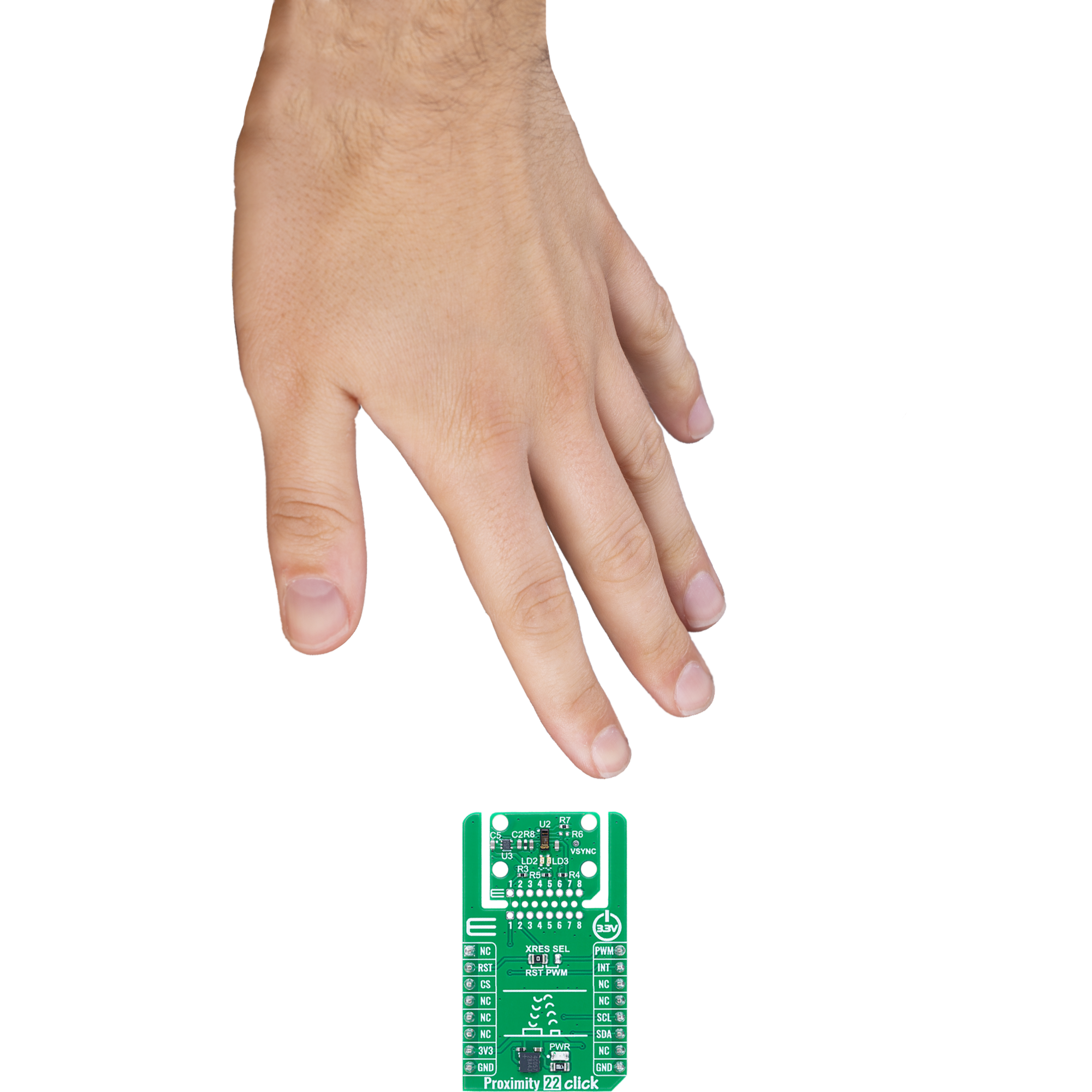
Ideal for display brightness tuning, gesture interaction, and ambient-aware user interfaces
A
A
Hardware Overview
How does it work?
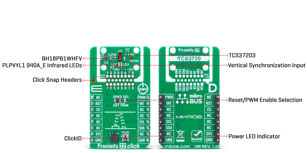
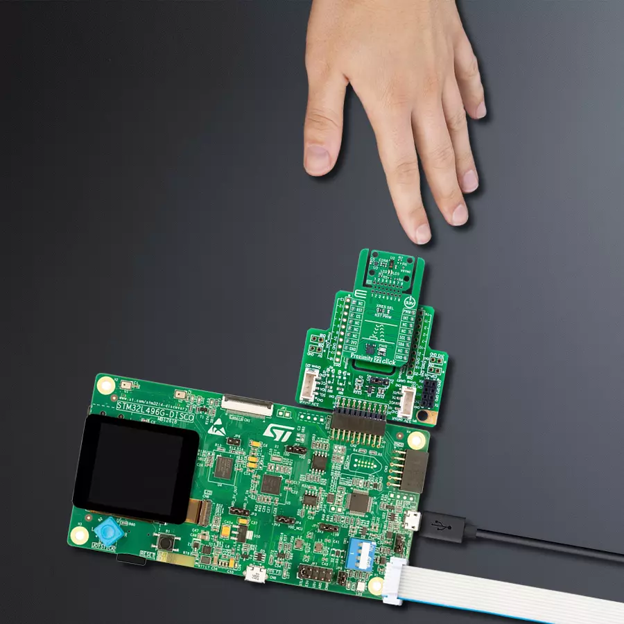
Proximity 22 Click is based on the TCS3720, an ALS/color and proximity sensor from ams OSRAM. This device offers a combination of ambient light, color (RGB), and proximity detection capabilities, making it ideal for applications requiring precise environmental awareness and object detection. The proximity function uses two OSRAM PLPVYL1 940A_E infrared LEDs operating at 940nm, positioned adjacent to the TCS3720 sensor to actively illuminate nearby objects with invisible IR light. The reflected signal is captured by the IR channel of the sensor, enabling reliable proximity measurements even in challenging low-light environments. The dual-LED configuration ensures enhanced coverage, delivering accurate detection across a broader range of object surfaces and angles. This Click board™ is ideal for display brightness and color management, as well as proximity detection in mobile and handheld devices. For ambient light and color sensing, the TCS3720 provides four concurrent sensing channels - Red, Green, Blue, and Clear - all protected by an integrated UV/IR blocking filter. This design allows precise measurement of ambient light intensity and color composition, enabling calculation of illuminance and correlated color temperature, which is particularly useful for dynamic brightness and
color management in display systems. The sensor architecture incorporates features such as self-maximizing dynamic range, ambient light subtraction, advanced crosstalk cancellation, and interrupt-driven I2C communication, ensuring optimal performance and system integration. This Click board™ is designed in a unique format supporting the newly introduced MIKROE feature called "Click Snap." Unlike the standardized version of Click boards, this feature allows the main sensor area to become movable by breaking the PCB, opening up many new possibilities for implementation. Thanks to the Snap feature, the TCS3720 can operate autonomously by accessing its signals directly on the pins marked 1-8. Additionally, the Snap part includes a specified and fixed screw hole position, enabling users to secure the Snap board in their desired location. As mentioned, this Click board™ uses an I2C interface with clock speeds of up to 400kHz, ensuring fast communication with the host MCU. The proximity engine recognizes detect/release events and produces a configurable interrupt (INT) whenever the proximity result crosses upper or lower threshold settings. In addition to the interrupt functionality, the Click board™ features a configurable jumper labeled XRES SEL, which
allows users to select the function of the sensor’s multipurpose pin. Depending on the jumper position and proper register configuration, this pin can be used either as a hardware reset for resetting the sensor or as a PWM input for synchronizing the proximity sensing engine with external modulation sources. The VSYNC test point on the Click board™ exposes the vertical synchronization input pin of the TCS3720 sensor. This pin allows the host MCU to externally trigger the start of a new color measurement cycle. While not connected to mikroBUS™ by default, it is available for advanced use cases where precise control of integration timing is required. The TCS3720 does not require a specific Power-Up sequence but requires a supply voltage of 1.8V to work correctly. Therefore, a small regulating LDO is used, the BH18PB1WHFV, providing a 1.8V out of mikroBUS™ power rail. This Click board™ can be operated only with a 3.3V logic voltage level. The board must perform appropriate logic voltage level conversion before using MCUs with different logic levels. It also comes equipped with a library containing functions and example code that can be used as a reference for further development.
Features overview
Development board
The 32L496GDISCOVERY Discovery kit serves as a comprehensive demonstration and development platform for the STM32L496AG microcontroller, featuring an Arm® Cortex®-M4 core. Designed for applications that demand a balance of high performance, advanced graphics, and ultra-low power consumption, this kit enables seamless prototyping for a wide range of embedded solutions. With its innovative energy-efficient
architecture, the STM32L496AG integrates extended RAM and the Chrom-ART Accelerator, enhancing graphics performance while maintaining low power consumption. This makes the kit particularly well-suited for applications involving audio processing, graphical user interfaces, and real-time data acquisition, where energy efficiency is a key requirement. For ease of development, the board includes an onboard ST-LINK/V2-1
debugger/programmer, providing a seamless out-of-the-box experience for loading, debugging, and testing applications without requiring additional hardware. The combination of low power features, enhanced memory capabilities, and built-in debugging tools makes the 32L496GDISCOVERY kit an ideal choice for prototyping advanced embedded systems with state-of-the-art energy efficiency.

Microcontroller Overview
MCU Card / MCU

Architecture
ARM Cortex-M4
MCU Memory (KB)
1024
Silicon Vendor
STMicroelectronics
Pin count
169
RAM (Bytes)
327680
Used MCU Pins
mikroBUS™ mapper
Take a closer look
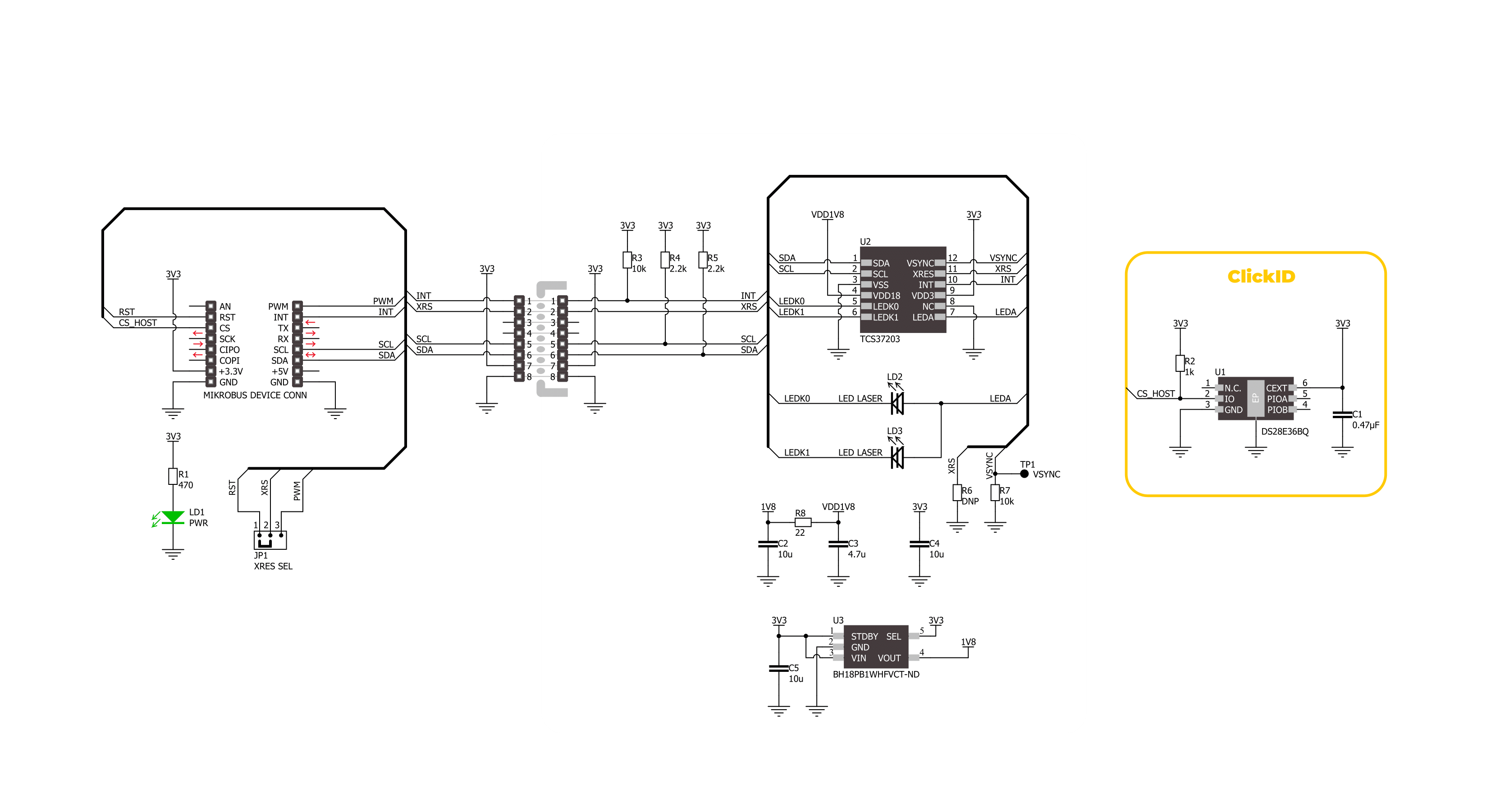
Click board™ Schematic
Step by step
Project assembly

Start by selecting your development board and Click board™. Begin with the Discovery kit with STM32L496AG MCU as your development board.


Software Support
Library Description
Proximity 22 Click demo application is developed using the NECTO Studio, ensuring compatibility with mikroSDK's open-source libraries and tools. Designed for plug-and-play implementation and testing, the demo is fully compatible with all development, starter, and mikromedia boards featuring a mikroBUS™ socket.
Example Description
This example demonstrates the use of the Proximity 22 Click board by reading and displaying proximity, ambient light (ALS), and temperature measurements. The data is read only when a new measurement is ready, indicated by an interrupt.
Key functions:
proximity22_cfg_setup- This function initializes Click configuration structure to initial values.proximity22_init- This function initializes all necessary pins and peripherals used for this Click board.proximity22_default_cfg- This function executes a default configuration of Proximity 22 Click board.proximity22_get_int_pin- This function returns the logic state of the INT pin.proximity22_read_data- This function reads proximity, temperature, and ALS data if available.
Application Init
Initializes the logger and the Proximity 22 Click driver, then sets the default configuration.
Application Task
Waits for a data ready interrupt and then reads the proximity, temperature, and ALS data (red, green, blue, and clear channels), displaying the results via UART approximately every 200 ms.
Open Source
Code example
The complete application code and a ready-to-use project are available through the NECTO Studio Package Manager for direct installation in the NECTO Studio. The application code can also be found on the MIKROE GitHub account.
/*!
 * @file main.c
 * @brief Proximity 22 Click example
 *
 * # Description
 * This example demonstrates the use of the Proximity 22 Click board by reading
 * and displaying proximity, ambient light (ALS), and temperature measurements.
 * The data is read only when a new measurement is ready, indicated by an interrupt.
 *
 * The demo application is composed of two sections:
 *
 * ## Application Init
 * Initializes the logger and the Proximity 22 Click driver, then sets the default configuration.
 *
 * ## Application Task
 * Waits for a data ready interrupt and then reads the proximity, temperature,
 * and ALS data (red, green, blue, and clear channels), displaying the results via UART
 * approximately every 200 ms.
 *
 * @author Stefan Filipovic
 *
 */

#include "board.h"
#include "log.h"
#include "proximity22.h"

static proximity22_t proximity22;
static log_t logger;

void application_init ( void )
{
    log_cfg_t log_cfg;  /**< Logger config object. */
    proximity22_cfg_t proximity22_cfg;  /**< Click config object. */

    /**
     * Logger initialization.
     * Default baud rate: 115200
     * Default log level: LOG_LEVEL_DEBUG
     * @note If USB_UART_RX and USB_UART_TX
     * are defined as HAL_PIN_NC, you will
     * need to define them manually for log to work.
     * See @b LOG_MAP_USB_UART macro definition for detailed explanation.
     */
    LOG_MAP_USB_UART( log_cfg );
    log_init( &logger, &log_cfg );
    log_info( &logger, " Application Init " );

    // Click initialization.
    proximity22_cfg_setup( &proximity22_cfg );
    PROXIMITY22_MAP_MIKROBUS( proximity22_cfg, MIKROBUS_1 );
    if ( I2C_MASTER_ERROR == proximity22_init( &proximity22, &proximity22_cfg ) )
    {
        log_error( &logger, " Communication init." );
        for ( ; ; );
    }

    if ( PROXIMITY22_ERROR == proximity22_default_cfg ( &proximity22 ) )
    {
        log_error( &logger, " Default configuration." );
        for ( ; ; );
    }

    log_info( &logger, " Application Task " );
}

void application_task ( void )
{
    proximity22_data_t meas_data;

    // Wait for a data ready interrupt
    while ( proximity22_get_int_pin ( &proximity22 ) );

    if ( PROXIMITY22_OK == proximity22_read_data ( &proximity22, &meas_data ) )
    {
        log_printf ( &logger, " Proximity: %u\r\n", meas_data.proximity );
        log_printf ( &logger, " Temperature: %.1f degC\r\n", meas_data.temperature );
        log_printf ( &logger, " ALS data (RGBC): %u;%u;%u;%u\r\n\n", meas_data.als.red,
                                                                     meas_data.als.green,
                                                                     meas_data.als.blue,
                                                                     meas_data.als.clear );
    }
}

int main ( void )
{
    /* Do not remove this line or clock might not be set correctly. */
    #ifdef PREINIT_SUPPORTED
    preinit();
    #endif

    application_init( );

    for ( ; ; )
    {
        application_task( );
    }

    return 0;
}

// ------------------------------------------------------------------------ END
Additional Support
Resources
Category:Proximity


