Create an easy-to-use/drop-in solution based on BLE 4.2 with RN4870 and PIC18F57Q43
Simplify connectivity

Published Feb 13, 2024
Click board™
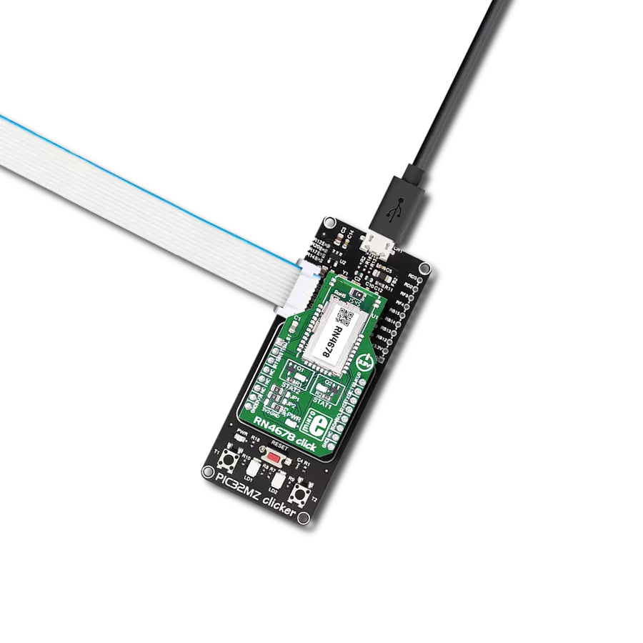
RN4870 click
Dev. board
Curiosity Nano with PIC18F57Q43
Compiler
NECTO Studio
MCU
PIC18F57Q43
Enable Bluetooth Low Energy connectivity for data exchange between devices.
A
A
Hardware Overview
How does it work?
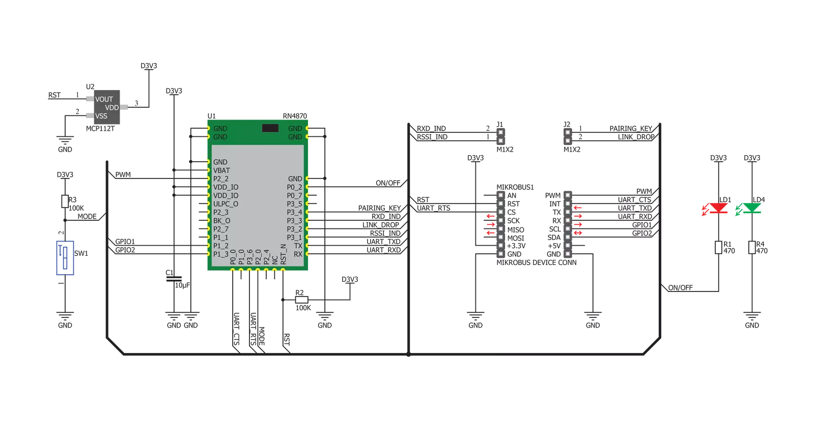
RN4870 Click is based on the RN4870, a Bluetooth® 4.2 low-energy module from Microchip. The Click is designed to run on a 3.3V power supply. It uses ASCII Command Interface over UART for communication with the target microcontroller, with additional functionality provided by the following pins on the mikroBUS™ line: PWM, INT, RST, CS. The RN4080 module from Microchip offers a complete solution to implement
Bluetooth 4.2 Low Energy connectivity. The host microcontroller can dynamically configure all products in the RN series with a few simple ASCII commands. The RN4870 supports peripheral and central Generic Access Profile (GAP) roles, actively scanning for other connectable devices instead of waiting for incoming connection requests. The peripherals are usually small, low-power devices that broadcast information to the central
device, like sensors and monitors. The central device can communicate with multiple peripherals. It also supports Remote Command mode, allowing a remote device to access Command mode remotely via Bluetooth. The module contains an integral ceramic chip antenna.

Features overview
Development board
PIC18F57Q43 Curiosity Nano evaluation kit is a cutting-edge hardware platform designed to evaluate microcontrollers within the PIC18-Q43 family. Central to its design is the inclusion of the powerful PIC18F57Q43 microcontroller (MCU), offering advanced functionalities and robust performance. Key features of this evaluation kit include a yellow user LED and a responsive
mechanical user switch, providing seamless interaction and testing. The provision for a 32.768kHz crystal footprint ensures precision timing capabilities. With an onboard debugger boasting a green power and status LED, programming and debugging become intuitive and efficient. Further enhancing its utility is the Virtual serial port (CDC) and a debug GPIO channel (DGI
GPIO), offering extensive connectivity options. Powered via USB, this kit boasts an adjustable target voltage feature facilitated by the MIC5353 LDO regulator, ensuring stable operation with an output voltage ranging from 1.8V to 5.1V, with a maximum output current of 500mA, subject to ambient temperature and voltage constraints.

Microcontroller Overview
MCU Card / MCU

Architecture
PIC
MCU Memory (KB)
128
Silicon Vendor
Microchip
Pin count
48
RAM (Bytes)
8196
You complete me!
Accessories
Curiosity Nano Base for Click boards is a versatile hardware extension platform created to streamline the integration between Curiosity Nano kits and extension boards, tailored explicitly for the mikroBUS™-standardized Click boards and Xplained Pro extension boards. This innovative base board (shield) offers seamless connectivity and expansion possibilities, simplifying experimentation and development. Key features include USB power compatibility from the Curiosity Nano kit, alongside an alternative external power input option for enhanced flexibility. The onboard Li-Ion/LiPo charger and management circuit ensure smooth operation for battery-powered applications, simplifying usage and management. Moreover, the base incorporates a fixed 3.3V PSU dedicated to target and mikroBUS™ power rails, alongside a fixed 5.0V boost converter catering to 5V power rails of mikroBUS™ sockets, providing stable power delivery for various connected devices.

Used MCU Pins
mikroBUS™ mapper
Take a closer look
Click board™ Schematic
Step by step
Project assembly

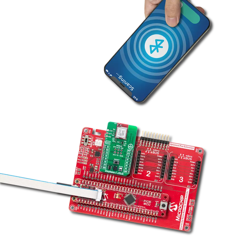
Start by selecting your development board and Click board™. Begin with the Curiosity Nano with PIC18F57Q43 as your development board.


Track your results in real time
Application Output
1. Application Output - In Debug mode, the 'Application Output' window enables real-time data monitoring, offering direct insight into execution results. Ensure proper data display by configuring the environment correctly using the provided tutorial.

2. UART Terminal - Use the UART Terminal to monitor data transmission via a USB to UART converter, allowing direct communication between the Click board™ and your development system. Configure the baud rate and other serial settings according to your project's requirements to ensure proper functionality. For step-by-step setup instructions, refer to the provided tutorial.

3. Plot Output - The Plot feature offers a powerful way to visualize real-time sensor data, enabling trend analysis, debugging, and comparison of multiple data points. To set it up correctly, follow the provided tutorial, which includes a step-by-step example of using the Plot feature to display Click board™ readings. To use the Plot feature in your code, use the function: plot(*insert_graph_name*, variable_name);. This is a general format, and it is up to the user to replace 'insert_graph_name' with the actual graph name and 'variable_name' with the parameter to be displayed.

Software Support
Library Description
This library contains API for RN4870 Click driver.
Key functions:
rn4870_read- This function gets message from 'void rn4870_receive function if flag was setrn4870_receive- This function receives character by waits for '#' - character to start parsing message, waits for '*' - character to stop parsing message and sets flag if whole and properly formated message is receivedrn4870_connect- This function connects to slave device with desired register address by secures the connection and entering data stream mode
Open Source
Code example
The complete application code and a ready-to-use project are available through the NECTO Studio Package Manager for direct installation in the NECTO Studio. The application code can also be found on the MIKROE GitHub account.
/*!
 * \file
 * \brief Rn4870 Click example
 *
 * # Description
 * This example reads and processes data from RN4870 Clicks.
 *
 * The demo application is composed of two sections :
 *
 * ## Application Init
 * Initializes UART driver. Initializes device and parser.
 *
 * ## Application Task
 * If 'MASTER' - connects to 'SLAVE', sends message and disconnects. If 'SLAVE' - waits for connect request
 * and message from 'MASTER' and LOGs received message.
 *
 * ## Additional Function
 * - rn4870_process ( ) - The general process of collecting presponce
 *                                   that sends a module.
 *
 *
 * \author MikroE Team
 *
 */
// ------------------------------------------------------------------- INCLUDES

#include "board.h"
#include "log.h"
#include "rn4870.h"
#include "string.h"

#define PROCESS_COUNTER 10
#define PROCESS_RX_BUFFER_SIZE 500
#define PROCESS_PARSER_BUFFER_SIZE 500

// ------------------------------------------------------------------ VARIABLES

// #define DEMO_APP_RECEIVER
#define DEMO_APP_TRANSMITER

static rn4870_t rn4870;
static log_t logger;

uint8_t RN4870_ADDR_MASTER[ 13 ] = {'D', 'F', '0', '0', '0', '0', '0', '6', '8', '7', '9', '0'};
uint8_t RN4870_ADDR_SLAVE[ 13 ] = {'D', 'F', '1', '1', '1', '1', '1', '6', '8', '7', '9', '0'};
uint8_t message_payload[ 17 ] = {'M', 'i', 'k', 'r', 'o', 'E', 'l', 'e', 'k', 't', 'r', 'o', 'n', 'i', 'k', 'a'};

uint8_t dev_type;
uint8_t receive_buffer[ 255 ];
uint8_t msg_flag = 0;
char *ptr;

// ------------------------------------------------------- ADDITIONAL FUNCTIONS

static void rn4870_process ( void )
{
    int32_t rsp_size;

    char uart_rx_buffer[ PROCESS_RX_BUFFER_SIZE ] = { 0 };
    uint8_t check_buf_cnt;


    rsp_size = rn4870_generic_read( &rn4870, &uart_rx_buffer, PROCESS_RX_BUFFER_SIZE );

    if ( rsp_size > 0 )
    {
        // Validation of the received data
        for ( check_buf_cnt = 0; check_buf_cnt < rsp_size; check_buf_cnt++ )
        {
            rn4870_receive( &rn4870, uart_rx_buffer[ check_buf_cnt ] );
        }
    }
}

// ------------------------------------------------------ APPLICATION FUNCTIONS

void application_init ( void )
{
    log_cfg_t log_cfg;
    rn4870_cfg_t cfg;

    /**
     * Logger initialization.
     * Default baud rate: 115200
     * Default log level: LOG_LEVEL_DEBUG
     * @note If USB_UART_RX and USB_UART_TX
     * are defined as HAL_PIN_NC, you will
     * need to define them manually for log to work.
     * See @b LOG_MAP_USB_UART macro definition for detailed explanation.
     */
    LOG_MAP_USB_UART( log_cfg );
    log_init( &logger, &log_cfg );
    log_info( &logger, "---- Application Init ----" );

    //  Click initialization.

    rn4870_cfg_setup( &cfg );
    RN4870_MAP_MIKROBUS( cfg, MIKROBUS_1 );
    rn4870_init( &rn4870, &cfg );
    Delay_ms ( 100 );

    dev_type = RN4870_DEVICETYPE_MASTER;

#ifdef DEMO_APP_TRANSMITER
    log_info( &logger, "RN4870 DEVICE TYPE MASTER" );
    rn4870_initialize( &rn4870, &RN4870_ADDR_MASTER[ 0 ] );
#endif
#ifdef DEMO_APP_RECEIVER
    log_info( &logger, "RN4870 DEVICE TYPE SLAVE" );
    rn4870_initialize( &rn4870, &RN4870_ADDR_SLAVE[ 0 ] );
    ptr = &receive_buffer[ 7 ];
#endif

    memset( &rn4870.device_buffer, 0, 255 );
    log_printf( &logger, " >>> app init done <<<  \r\n" );
}

void application_task ( void )
{
    rn4870_process(  );
#ifdef DEMO_APP_TRANSMITER
    rn4870_connect( &rn4870, &RN4870_ADDR_SLAVE[ 0 ] );
    Delay_ms ( 100 );
    log_printf( &logger, ">>> sending data  <<<\r\n" );
    rn4870_send( &rn4870, RN4870_MTYPE_MSG, RN4870_DTYPE_STRING, RN4870_ID_MASTER, &message_payload[ 0 ] );
    Delay_ms ( 100 );
    rn4870_disconnect( &rn4870 );
    Delay_ms ( 100 );
#endif

#ifdef DEMO_APP_RECEIVER
    msg_flag = rn4870_read( &rn4870, &receive_buffer[ 0 ] );

    if ( msg_flag == 1 )
    {
        log_printf( &logger, ">>> data received <<<\r\n" );
        log_printf( &logger, ">>> data : " );
        log_printf( &logger, "%s\r\n", ptr );
    }
#endif
}

int main ( void )
{
    /* Do not remove this line or clock might not be set correctly. */
    #ifdef PREINIT_SUPPORTED
    preinit();
    #endif

    application_init( );

    for ( ; ; )
    {
        application_task( );
    }

    return 0;
}


// ------------------------------------------------------------------------ END
Additional Support
Resources
Category:BT/BLE