Expand the number of input/output (I/O) pins in your system with TCAL9538 and PIC18F57Q43
8-bit I2C-bus I/O expander in a Click Snap form factor
Published Sep 24, 2024
Click board™
Expand 19 Click
Dev. board
Curiosity Nano with PIC18F57Q43
Compiler
NECTO Studio
MCU
PIC18F57Q43
Add additional general I/O pins for a variety of applications
A
A
Hardware Overview
How does it work?
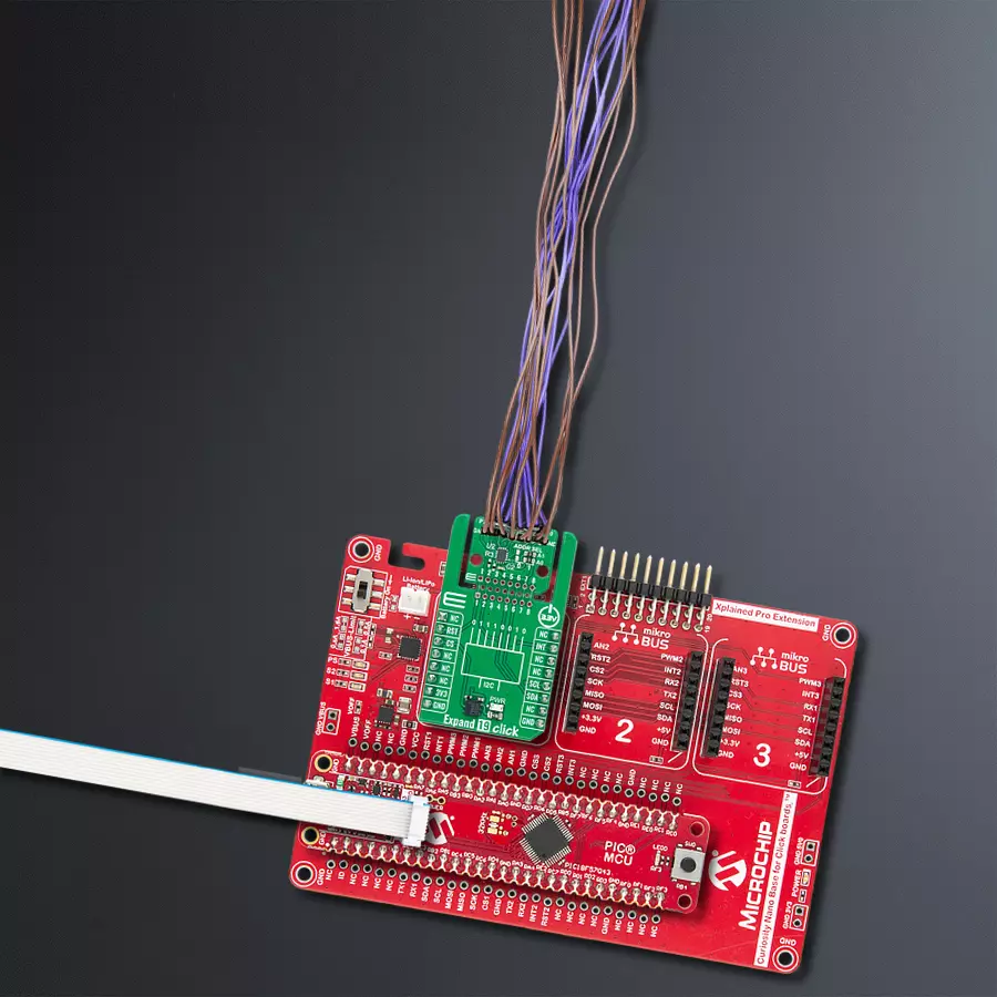
Expand 19 Click is based on the TCAL9538, an 8-bit I2C-bus I/O expander from Texas Instruments. This Click board™ provides a simple solution for applications that require additional input/output lines, such as controlling switches, sensors, push-buttons, LEDs, and more. Operating at 3.3V, the TCAL9538 allows easy integration into existing systems using the standard two-wire I2C communication protocol. At its core, the TCAL9538 features 8-bit data registers that enable users to configure the I/O pins as inputs or outputs. Upon power-up or a software reset, all I/Os are set as inputs by default. However, they can be reconfigured by the host microcontroller through the Configuration registers. The data for each pin is stored in dedicated Input Port or Output Port registers, which are accessible for reading by the host MCU. Additionally, the polarity of the Input Port can be adjusted via the Polarity Inversion register, offering flexibility in design and signal interpretation. This Click board™ is designed in a
unique format supporting the newly introduced MIKROE feature called "Click Snap." Unlike the standardized version of Click boards, this feature allows the main sensor area to become movable by breaking the PCB, opening up many new possibilities for implementation. Thanks to the Snap feature, the TCAL9538 can operate autonomously by accessing its signals directly on the pins marked 1-8. Additionally, the Snap part includes a specified and fixed screw hole position, enabling users to secure the Snap board in their desired location. One of the key features of the TCAL9538 is its Agile I/O functionality, which enhances the performance of the I/O ports. This includes configurable output drive strength, programmable pull-up and pull-down resistors, latchable inputs, and maskable interrupts. The device also offers programmable open-drain or push-pull output modes, making it adaptable to various application requirements. These Agile I/O features provide the flexibility to optimize your design for power
consumption, speed, and electromagnetic interference (EMI). Expand 19 Click uses an I2C interface with clock speeds of up to 1MHz, ensuring fast and efficient communication with the host MCU. The I2C address can be easily configured via onboard jumpers, allowing multiple devices tocoexist on the same bus. Additionally, the board features an interrupt (INT) pin triggered whenever there is a change in the state of any input port, ensuring real-time response to external events, and a reset (RST) pin for power cycling to return the device to its default state. This ensures reliable operation and easy recovery in case of unexpected issues. This Click board™ can be operated only with a 3.3V logic voltage level. The board must perform appropriate logic voltage level conversion before using MCUs with different logic levels. Also, it comes equipped with a library containing functions and an example code that can be used as a reference for further development.

Features overview
Development board
PIC18F57Q43 Curiosity Nano evaluation kit is a cutting-edge hardware platform designed to evaluate microcontrollers within the PIC18-Q43 family. Central to its design is the inclusion of the powerful PIC18F57Q43 microcontroller (MCU), offering advanced functionalities and robust performance. Key features of this evaluation kit include a yellow user LED and a responsive
mechanical user switch, providing seamless interaction and testing. The provision for a 32.768kHz crystal footprint ensures precision timing capabilities. With an onboard debugger boasting a green power and status LED, programming and debugging become intuitive and efficient. Further enhancing its utility is the Virtual serial port (CDC) and a debug GPIO channel (DGI
GPIO), offering extensive connectivity options. Powered via USB, this kit boasts an adjustable target voltage feature facilitated by the MIC5353 LDO regulator, ensuring stable operation with an output voltage ranging from 1.8V to 5.1V, with a maximum output current of 500mA, subject to ambient temperature and voltage constraints.

Microcontroller Overview
MCU Card / MCU

Architecture
PIC
MCU Memory (KB)
128
Silicon Vendor
Microchip
Pin count
48
RAM (Bytes)
8196
You complete me!
Accessories
Curiosity Nano Base for Click boards is a versatile hardware extension platform created to streamline the integration between Curiosity Nano kits and extension boards, tailored explicitly for the mikroBUS™-standardized Click boards and Xplained Pro extension boards. This innovative base board (shield) offers seamless connectivity and expansion possibilities, simplifying experimentation and development. Key features include USB power compatibility from the Curiosity Nano kit, alongside an alternative external power input option for enhanced flexibility. The onboard Li-Ion/LiPo charger and management circuit ensure smooth operation for battery-powered applications, simplifying usage and management. Moreover, the base incorporates a fixed 3.3V PSU dedicated to target and mikroBUS™ power rails, alongside a fixed 5.0V boost converter catering to 5V power rails of mikroBUS™ sockets, providing stable power delivery for various connected devices.

Used MCU Pins
mikroBUS™ mapper
Take a closer look
Click board™ Schematic

Step by step
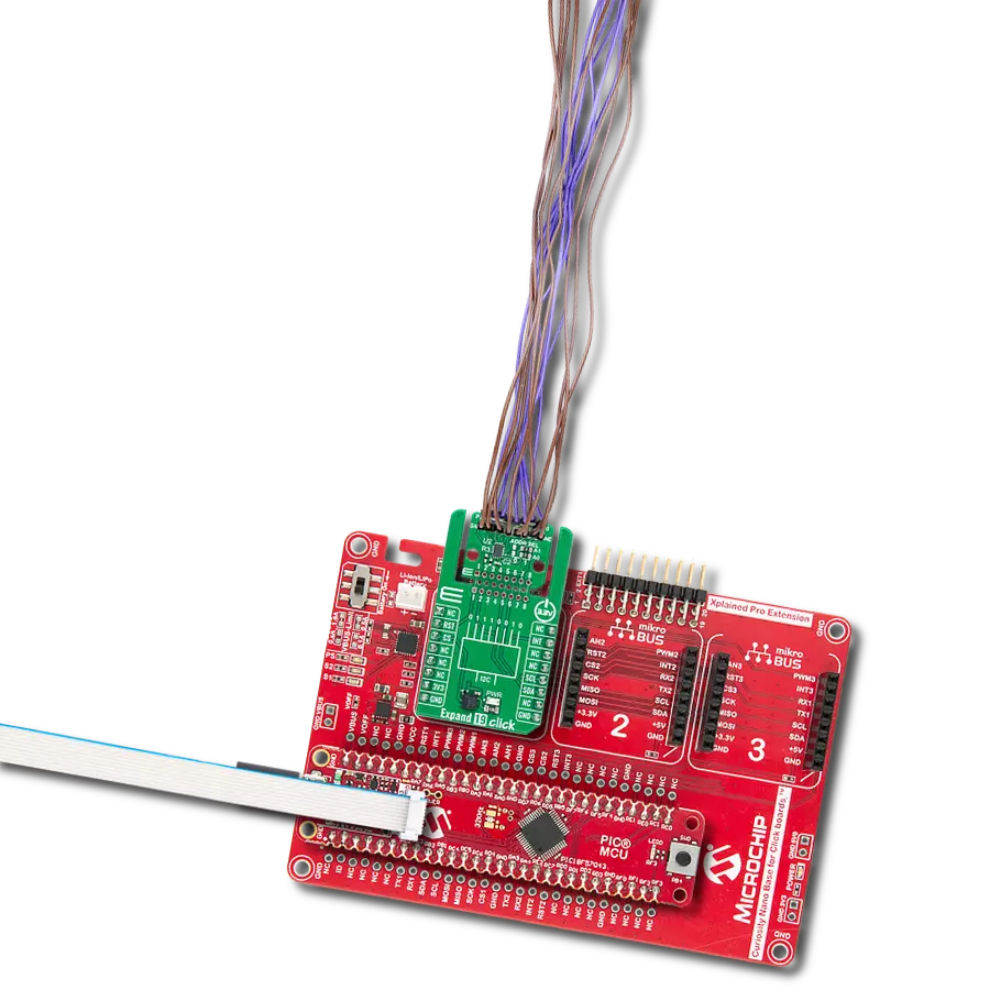
Project assembly

Start by selecting your development board and Click board™. Begin with the Curiosity Nano with PIC18F57Q43 as your development board.


Software Support
Library Description
This library contains API for Expand 19 Click driver.
Key functions:
expand19_set_pin_direction- This function sets the direction of the selected pins.expand19_set_all_pins_value- This function sets the value of all output pins.expand19_read_port_value- This function reads the value of all input pins.
Open Source
Code example
The complete application code and a ready-to-use project are available through the NECTO Studio Package Manager for direct installation in the NECTO Studio. The application code can also be found on the MIKROE GitHub account.
/*!
 * @file main.c
 * @brief Expand 19 Click example
 *
 * # Description
 * This example demonstrates the use of Expand 19 Click board by setting and
 * reading the port state.
 *
 * The demo application is composed of two sections :
 *
 * ## Application Init
 * Initializes the driver and performs the Click default configuration which sets
 * the pins 0-3 as output and others as input with pull-up enabled.
 *
 * ## Application Task
 * Sets the output pins and then reads the status of all pins and
 * displays the results on the USB UART approximately once per second.
 *
 * @author Stefan Filipovic
 *
 */

#include "board.h"
#include "log.h"
#include "expand19.h"

static expand19_t expand19;
static log_t logger;

void application_init ( void )
{
    log_cfg_t log_cfg;  /**< Logger config object. */
    expand19_cfg_t expand19_cfg;  /**< Click config object. */

    /**
     * Logger initialization.
     * Default baud rate: 115200
     * Default log level: LOG_LEVEL_DEBUG
     * @note If USB_UART_RX and USB_UART_TX
     * are defined as HAL_PIN_NC, you will
     * need to define them manually for log to work.
     * See @b LOG_MAP_USB_UART macro definition for detailed explanation.
     */
    LOG_MAP_USB_UART( log_cfg );
    log_init( &logger, &log_cfg );
    log_info( &logger, " Application Init " );

    // Click initialization.
    expand19_cfg_setup( &expand19_cfg );
    EXPAND19_MAP_MIKROBUS( expand19_cfg, MIKROBUS_1 );
    if ( I2C_MASTER_ERROR == expand19_init( &expand19, &expand19_cfg ) )
    {
        log_error( &logger, " Communication init." );
        for ( ; ; );
    }

    if ( EXPAND19_ERROR == expand19_default_cfg ( &expand19 ) )
    {
        log_error( &logger, " Default configuration." );
        for ( ; ; );
    }

    log_info( &logger, " Application Task " );
}

void application_task ( void )
{
    uint8_t port_value = 0;
    for ( uint16_t pin_num = EXPAND19_PIN_0_MASK; pin_num <= EXPAND19_PIN_3_MASK; pin_num <<= 1 )
    {
        expand19_set_all_pins_value( &expand19, pin_num );

        expand19_read_port_value( &expand19, &port_value );
        log_printf( &logger, " Port status: 0x%.2X\r\n", ( uint16_t ) port_value );

        Delay_ms( 1000 );
    }
}

int main ( void )
{
    /* Do not remove this line or clock might not be set correctly. */
    #ifdef PREINIT_SUPPORTED
    preinit();
    #endif

    application_init( );

    for ( ; ; )
    {
        application_task( );
    }

    return 0;
}

// ------------------------------------------------------------------------ END
Additional Support
Resources
Category:Port expander