Enable effortless peripheral connection and control with SX1509QB and STM32F446RE
Control beyond limits: Multi-port I/O, endless possibilities!
Published Oct 08, 2024
Click board™
Expand 9 Click
Dev. board
Nucleo 64 with STM32F446RE MCU
Compiler
NECTO Studio
MCU
STM32F446RE
Revolutionize data acquisition and control applications by integrating our multi-port I/O expander, simplifying the management of multiple inputs and outputs with bi-directional flexibility
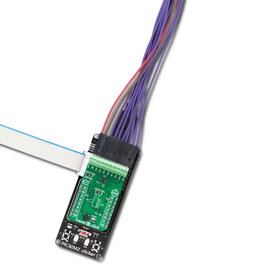
A
A
Hardware Overview
How does it work?
Expand 9 Click is based on the SX1509QB, a 16-channel lowest voltage level shifting GPIO expander from Semtech Corporation. The expander devices, like this one, can provide additional control and monitoring when the MCU has insufficient I/O ports or in systems where serial communication and control from a remote location are advantageous. The SX1509QB has a built-in level shifting feature, making it highly flexible in power supply systems where communication between incompatible I/O voltages is required, thus eliminating extra-level translating circuits. The SX1509QB features a fully programmable LED driver with an internal oscillator for enhanced lighting control, such as intensity (via 256-step PWM), blinking, and breathing (fade In/Out), which makes them highly versatile for a wide range of LED applications. Also, keypad applications are supported with an on-chip scanning engine, enabling continuous
monitoring of up to 64 keys (8x8 matrix) without additional host interaction, reducing bus activity. Expand 9 Click communicates with MCU using the standard I2C 2-Wire interface to read data and configure settings, supporting a Fast Mode operation up to 400kHz. The selection of the I2C slave address is also possible using the ADD pin routed to the AN pin of the mikroBUS™ socket. This way, the SX1509QB provides the opportunity of the two possible different I2C addresses by setting the ADD pin to an appropriate logic state. In addition to selecting a Slave address, the SX1509QB can generate mask-programmable interrupts based on a falling/rising edge of any of its GPIO lines. A dedicated interrupt pin, routed to the INT pin of the mikroBUS™ socket, indicates to a host controller that a state change occurred on one or more of the expand lines, while the RST pin of the mikroBUS™ socket represents a Reset feature used to reset the chip at any time. Each
GPIO on I/O Expander channels is programmable via a bank of 8-bit configuration registers, including data, direction, pull-up/pull-down, interrupt mask, and interrupt registers. The user is also given an option of selecting the expander port supply voltage, which is realized by two onboard switches labeled as VCCA and VCCB, allowing one to choose between 3.3V and 1.8V. To obtain 1.8V, a small LDO regulator, AP2112 from Dialog Incorporated, is added to provide 1.8V out of mikroBUS™ power rail. This Click board™ can be operated only with a 3.3V logic voltage level. The board must perform appropriate logic voltage level conversion before using MCUs with different logic levels. Also, it comes equipped with a library containing functions and an example code that can be used as a reference for further development.


Features overview
Development board
Nucleo-64 with STM32F446RE MCU offers a cost-effective and adaptable platform for developers to explore new ideas and prototype their designs. This board harnesses the versatility of the STM32 microcontroller, enabling users to select the optimal balance of performance and power consumption for their projects. It accommodates the STM32 microcontroller in the LQFP64 package and includes essential components such as a user LED, which doubles as an ARDUINO® signal, alongside user and reset push-buttons, and a 32.768kHz crystal oscillator for precise timing operations. Designed with expansion and flexibility in mind, the Nucleo-64 board features an ARDUINO® Uno V3 expansion connector and ST morpho extension pin
headers, granting complete access to the STM32's I/Os for comprehensive project integration. Power supply options are adaptable, supporting ST-LINK USB VBUS or external power sources, ensuring adaptability in various development environments. The board also has an on-board ST-LINK debugger/programmer with USB re-enumeration capability, simplifying the programming and debugging process. Moreover, the board is designed to simplify advanced development with its external SMPS for efficient Vcore logic supply, support for USB Device full speed or USB SNK/UFP full speed, and built-in cryptographic features, enhancing both the power efficiency and security of projects. Additional connectivity is
provided through dedicated connectors for external SMPS experimentation, a USB connector for the ST-LINK, and a MIPI® debug connector, expanding the possibilities for hardware interfacing and experimentation. Developers will find extensive support through comprehensive free software libraries and examples, courtesy of the STM32Cube MCU Package. This, combined with compatibility with a wide array of Integrated Development Environments (IDEs), including IAR Embedded Workbench®, MDK-ARM, and STM32CubeIDE, ensures a smooth and efficient development experience, allowing users to fully leverage the capabilities of the Nucleo-64 board in their projects.

Microcontroller Overview
MCU Card / MCU

Architecture
ARM Cortex-M4
MCU Memory (KB)
512
Silicon Vendor
STMicroelectronics
Pin count
64
RAM (Bytes)
131072
You complete me!
Accessories
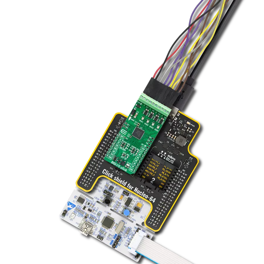
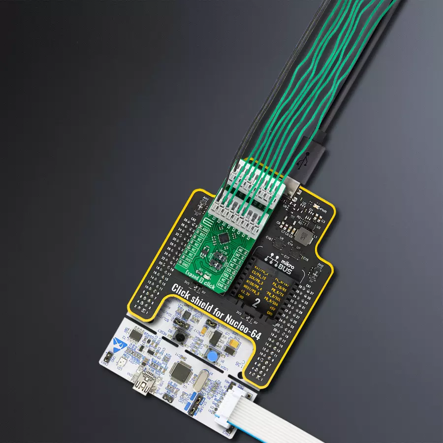
Click Shield for Nucleo-64 comes equipped with two proprietary mikroBUS™ sockets, allowing all the Click board™ devices to be interfaced with the STM32 Nucleo-64 board with no effort. This way, Mikroe allows its users to add any functionality from our ever-growing range of Click boards™, such as WiFi, GSM, GPS, Bluetooth, ZigBee, environmental sensors, LEDs, speech recognition, motor control, movement sensors, and many more. More than 1537 Click boards™, which can be stacked and integrated, are at your disposal. The STM32 Nucleo-64 boards are based on the microcontrollers in 64-pin packages, a 32-bit MCU with an ARM Cortex M4 processor operating at 84MHz, 512Kb Flash, and 96KB SRAM, divided into two regions where the top section represents the ST-Link/V2 debugger and programmer while the bottom section of the board is an actual development board. These boards are controlled and powered conveniently through a USB connection to program and efficiently debug the Nucleo-64 board out of the box, with an additional USB cable connected to the USB mini port on the board. Most of the STM32 microcontroller pins are brought to the IO pins on the left and right edge of the board, which are then connected to two existing mikroBUS™ sockets. This Click Shield also has several switches that perform functions such as selecting the logic levels of analog signals on mikroBUS™ sockets and selecting logic voltage levels of the mikroBUS™ sockets themselves. Besides, the user is offered the possibility of using any Click board™ with the help of existing bidirectional level-shifting voltage translators, regardless of whether the Click board™ operates at a 3.3V or 5V logic voltage level. Once you connect the STM32 Nucleo-64 board with our Click Shield for Nucleo-64, you can access hundreds of Click boards™, working with 3.3V or 5V logic voltage levels.

Used MCU Pins
mikroBUS™ mapper
Take a closer look
Click board™ Schematic

Step by step
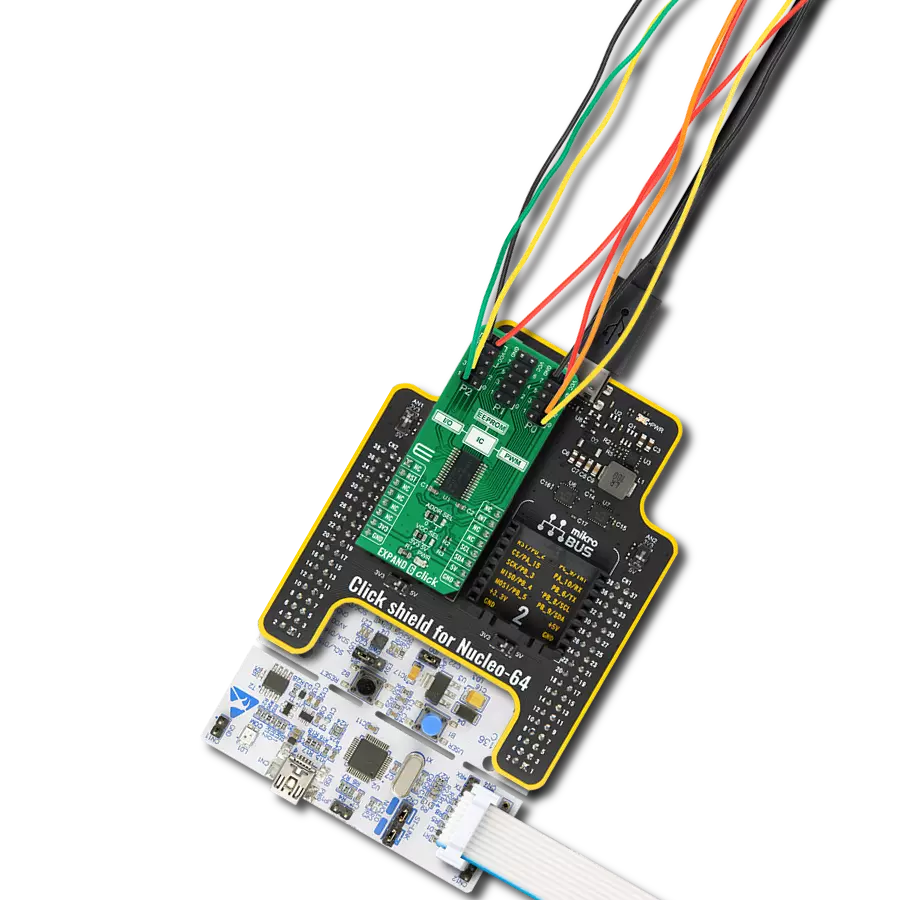
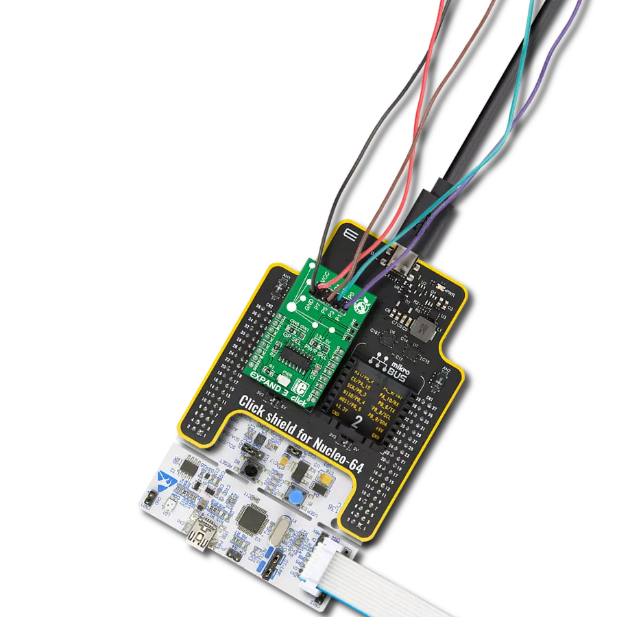
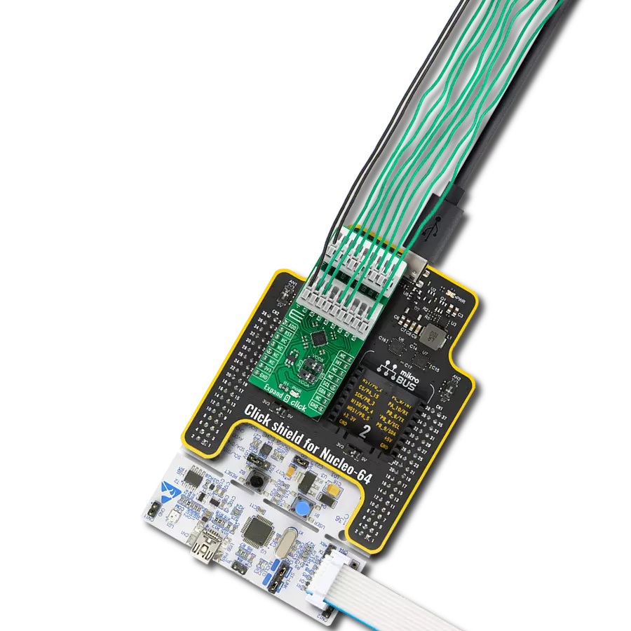
Project assembly
Start by selecting your development board and Click board™. Begin with the Nucleo 64 with STM32F446RE MCU as your development board.


Track your results in real time
Application Output
1. Application Output - In Debug mode, the 'Application Output' window enables real-time data monitoring, offering direct insight into execution results. Ensure proper data display by configuring the environment correctly using the provided tutorial.

2. UART Terminal - Use the UART Terminal to monitor data transmission via a USB to UART converter, allowing direct communication between the Click board™ and your development system. Configure the baud rate and other serial settings according to your project's requirements to ensure proper functionality. For step-by-step setup instructions, refer to the provided tutorial.

3. Plot Output - The Plot feature offers a powerful way to visualize real-time sensor data, enabling trend analysis, debugging, and comparison of multiple data points. To set it up correctly, follow the provided tutorial, which includes a step-by-step example of using the Plot feature to display Click board™ readings. To use the Plot feature in your code, use the function: plot(*insert_graph_name*, variable_name);. This is a general format, and it is up to the user to replace 'insert_graph_name' with the actual graph name and 'variable_name' with the parameter to be displayed.

Software Support
Library Description
This library contains API for Expand 9 Click driver.
Key functions:
expand9_set_ch_output_state- Expand 9 set channel output state functionexpand9_led_driver_config- Expand 9 LED driver configuration functionexpand9_soft_reset- Expand 9 software reset function
Open Source
Code example
The complete application code and a ready-to-use project are available through the NECTO Studio Package Manager for direct installation in the NECTO Studio. The application code can also be found on the MIKROE GitHub account.
/*!
 * @file main.c
 * @brief Expand9 Click example
 *
 * # Description
 * This is an example that demonstrates the use of the Expand 9 Click board™.
 * The library initializes and defines the I2C bus drivers
 * to write and read data from registers.
 *
 * The demo application is composed of two sections :
 *
 * ## Application Init
 * The initialization of I2C  module, log UART, and additional pins.
 * After driver initialization the app set default settings.
 *
 * ## Application Task
 * This is an example that demonstrates the use of the Expand 9 Click board™.
 * This example shows the capabilities of the Expand 9 Click by toggling each of 16 available channels.
 * Results are being sent to the Usart Terminal where you can track their changes.
 *
 * @author Nenad Filipovic
 *
 */

#include "board.h"
#include "log.h"
#include "expand9.h"

static expand9_t expand9;
static log_t logger;

void application_init ( void )
{
    log_cfg_t log_cfg;  /**< Logger config object. */
    expand9_cfg_t expand9_cfg;  /**< Click config object. */

    /**
     * Logger initialization.
     * Default baud rate: 115200
     * Default log level: LOG_LEVEL_DEBUG
     * @note If USB_UART_RX and USB_UART_TX
     * are defined as HAL_PIN_NC, you will
     * need to define them manually for log to work.
     * See @b LOG_MAP_USB_UART macro definition for detailed explanation.
     */
    LOG_MAP_USB_UART( log_cfg );
    log_init( &logger, &log_cfg );
    log_info( &logger, " Application Init " );

    // Click initialization.
    expand9_cfg_setup( &expand9_cfg );
    EXPAND9_MAP_MIKROBUS( expand9_cfg, MIKROBUS_1 );
    err_t init_flag = expand9_init( &expand9, &expand9_cfg );
    if ( I2C_MASTER_ERROR == init_flag )
    {
        log_error( &logger, " Application Init Error. " );
        log_info( &logger, " Please, run program again... " );

        for ( ; ; );
    }

    expand9_default_cfg ( &expand9 );
    log_info( &logger, " Application Task " );
    Delay_ms ( 100 );
}

void application_task ( void )
{
    expand9_soft_reset( &expand9 );
    Delay_ms ( 100 );

    for ( uint8_t cnt = 0; cnt < 16; cnt++ )
    {
        expand9_set_ch_output_state( &expand9, cnt, CH_OUTPUT_ON );
        Delay_ms ( 100 );
        expand9_set_ch_output_state( &expand9, cnt, CH_OUTPUT_OFF );
        Delay_ms ( 100 );
    }

    for ( uint8_t cnt = 15; cnt > 0; cnt-- )
    {
        expand9_set_ch_output_state( &expand9, cnt, CH_OUTPUT_ON );
        Delay_ms ( 100 );
        expand9_set_ch_output_state( &expand9, cnt, CH_OUTPUT_OFF );
        Delay_ms ( 100 );
    }

    expand9_soft_reset( &expand9 );
    Delay_ms ( 100 );

    for ( uint8_t cnt = 0; cnt < 16; cnt++ )
    {
        expand9_led_driver_config( &expand9, cnt, EXPAND9_FREQ_DIV_1, EXPAND9_LED_MODE_LINEAR );
        expand9_set_intensity( &expand9, cnt, 10 );
        Delay_ms ( 100 );
        expand9_led_driver_config( &expand9, cnt, EXPAND9_FREQ_DIV_1, EXPAND9_LED_MODE_LINEAR );
        expand9_set_intensity( &expand9, cnt, 200 );
        Delay_ms ( 100 );
    }

    for ( uint8_t cnt = 15; cnt > 0; cnt-- )
    {
        expand9_led_driver_config( &expand9, cnt, EXPAND9_FREQ_DIV_1, EXPAND9_LED_MODE_LINEAR );
        expand9_set_intensity( &expand9, cnt, 200 );
        Delay_ms ( 100 );
        expand9_led_driver_config( &expand9, cnt, EXPAND9_FREQ_DIV_1, EXPAND9_LED_MODE_LINEAR );
        expand9_set_intensity( &expand9, cnt, 10 );
        Delay_ms ( 100 );
    }
}

int main ( void )
{
    /* Do not remove this line or clock might not be set correctly. */
    #ifdef PREINIT_SUPPORTED
    preinit();
    #endif

    application_init( );

    for ( ; ; )
    {
        application_task( );
    }

    return 0;
}

// ------------------------------------------------------------------------ END
Additional Support
Resources
Category:Port expander