Measure distances from 1mm to 1300mm with great accuracy with VL53L4ED and PIC18F57Q43
Proximity sensing and short-range distance measurement solution

Published Sep 10, 2024
Click board™
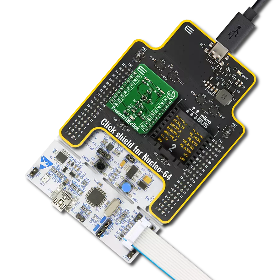
Proximity 21 Click
Dev. board
Curiosity Nano with PIC18F57Q43
Compiler
NECTO Studio
MCU
PIC18F57Q43
Enhance your projects with precise proximity sensing and reliable distance measurements, even in challenging ambient light conditions
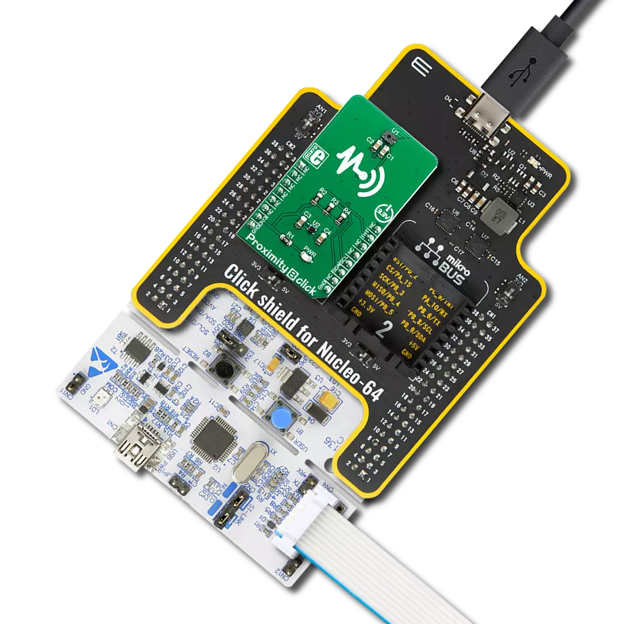
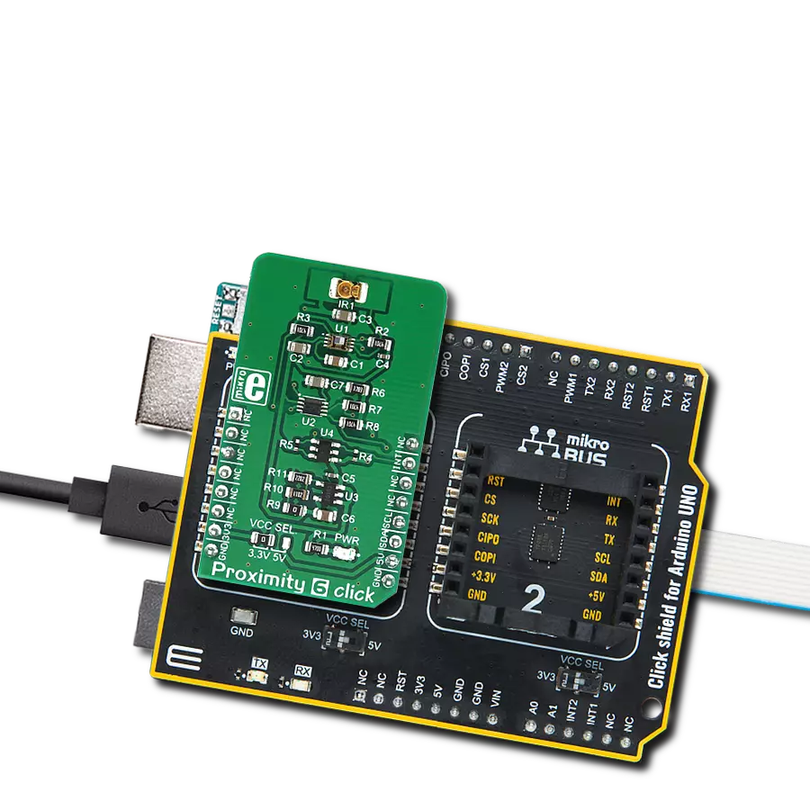
A
A
Hardware Overview
How does it work?
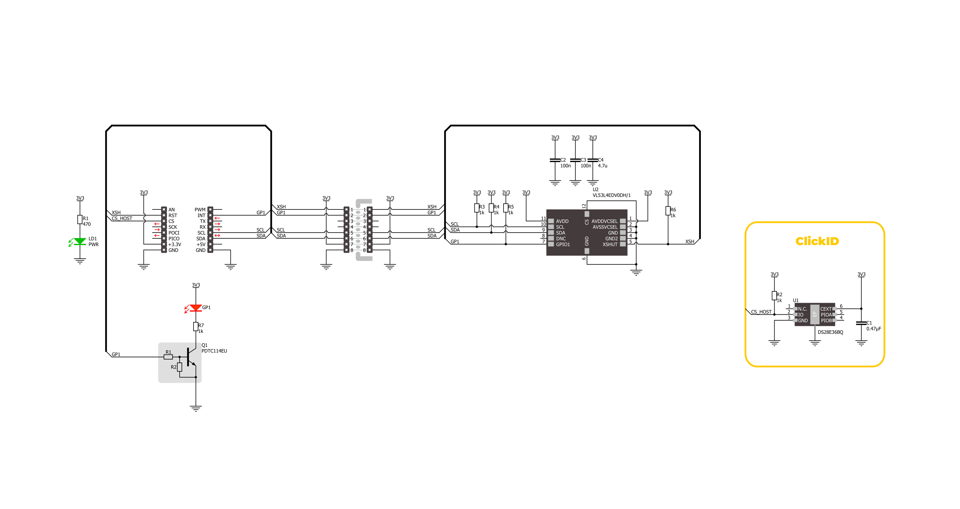
Proximity 21 Click is based on the VL53L4ED, a high-precision Time-of-Flight (ToF) proximity sensor from STMicroelectronics, known for its extended temperature capability. This sensor is made for accurate short-range measurements, offering a field of view (FoV) of 18° and measuring distances from 1mm up to 1300mm under standard conditions and up to 1150mm in extended temperature environments. The VL53L4ED operates effectively in temperatures ranging from -40°C to 105°C, ensuring consistent performance even in harsh industrial settings. Additionally, it provides reliable distance measurements up to 800mm even in ambient light conditions of 5klx, making it ideal for applications requiring precise proximity sensing such as industrial automation, security systems, robotics, smart lighting, and biometric distance measurements. The VL53L4ED uses STMicroelectronics' FlightSense technology,
allowing it to measure absolute distances regardless of target color or reflectance. It includes a SPAD (single photon avalanche diode) array, enhancing its performance across ambient lighting conditions and various cover glass materials. Additionally, the sensor integrates a VCSEL (vertical-cavity surface-emitting laser) that emits an invisible 940nm IR light, certified as Class 1 eye-safe. Proximity 21 Click is designed in a unique format supporting the newly introduced MIKROE feature called "Click Snap." Unlike the standardized version of Click boards, this feature allows the main IC area to become movable by breaking the PCB, opening up many new possibilities for implementation. Thanks to the Snap feature, the VL53L4ED can operate autonomously by accessing its signals directly on the pins marked 1-8. Additionally, the Snap part includes a specified and fixed screw hole position, enabling users to secure
the Snap board in their desired location. This Click board™ uses a standard 2-wire I2C interface for communication with the host MCU, supporting Fast Mode Plus with a clock frequency of up to 1MHz. In addition to the interface pins, the sensor also uses the XSH shutdown pin from the mikroBUS™ socket for device power-up and boot sequence. The device can be fully powered down when not in use and then reactivated by the host MCU using the XSH pin. It also uses the GP1 pin from the mikroBUS™ socket as a hardware interrupt, along with a red GP1 LED indicator, to signal and visually indicate various conditions. This Click board™ can be operated only with a 3.3V logic voltage level. The board must perform appropriate logic voltage level conversion before using MCUs with different logic levels. Also, it comes equipped with a library containing functions and an example code that can be used as a reference for further development.

Features overview
Development board
PIC18F57Q43 Curiosity Nano evaluation kit is a cutting-edge hardware platform designed to evaluate microcontrollers within the PIC18-Q43 family. Central to its design is the inclusion of the powerful PIC18F57Q43 microcontroller (MCU), offering advanced functionalities and robust performance. Key features of this evaluation kit include a yellow user LED and a responsive
mechanical user switch, providing seamless interaction and testing. The provision for a 32.768kHz crystal footprint ensures precision timing capabilities. With an onboard debugger boasting a green power and status LED, programming and debugging become intuitive and efficient. Further enhancing its utility is the Virtual serial port (CDC) and a debug GPIO channel (DGI
GPIO), offering extensive connectivity options. Powered via USB, this kit boasts an adjustable target voltage feature facilitated by the MIC5353 LDO regulator, ensuring stable operation with an output voltage ranging from 1.8V to 5.1V, with a maximum output current of 500mA, subject to ambient temperature and voltage constraints.

Microcontroller Overview
MCU Card / MCU

Architecture
PIC
MCU Memory (KB)
128
Silicon Vendor
Microchip
Pin count
48
RAM (Bytes)
8196
You complete me!
Accessories
Curiosity Nano Base for Click boards is a versatile hardware extension platform created to streamline the integration between Curiosity Nano kits and extension boards, tailored explicitly for the mikroBUS™-standardized Click boards and Xplained Pro extension boards. This innovative base board (shield) offers seamless connectivity and expansion possibilities, simplifying experimentation and development. Key features include USB power compatibility from the Curiosity Nano kit, alongside an alternative external power input option for enhanced flexibility. The onboard Li-Ion/LiPo charger and management circuit ensure smooth operation for battery-powered applications, simplifying usage and management. Moreover, the base incorporates a fixed 3.3V PSU dedicated to target and mikroBUS™ power rails, alongside a fixed 5.0V boost converter catering to 5V power rails of mikroBUS™ sockets, providing stable power delivery for various connected devices.

Used MCU Pins
mikroBUS™ mapper
Take a closer look
Click board™ Schematic
Step by step
Project assembly

Start by selecting your development board and Click board™. Begin with the Curiosity Nano with PIC18F57Q43 as your development board.


Track your results in real time
Application Output
1. Application Output - In Debug mode, the 'Application Output' window enables real-time data monitoring, offering direct insight into execution results. Ensure proper data display by configuring the environment correctly using the provided tutorial.

2. UART Terminal - Use the UART Terminal to monitor data transmission via a USB to UART converter, allowing direct communication between the Click board™ and your development system. Configure the baud rate and other serial settings according to your project's requirements to ensure proper functionality. For step-by-step setup instructions, refer to the provided tutorial.

3. Plot Output - The Plot feature offers a powerful way to visualize real-time sensor data, enabling trend analysis, debugging, and comparison of multiple data points. To set it up correctly, follow the provided tutorial, which includes a step-by-step example of using the Plot feature to display Click board™ readings. To use the Plot feature in your code, use the function: plot(*insert_graph_name*, variable_name);. This is a general format, and it is up to the user to replace 'insert_graph_name' with the actual graph name and 'variable_name' with the parameter to be displayed.

Software Support
Library Description
This library contains API for Proximity 21 Click driver.
Key functions:
proximity21_get_gpio1_pin- This function returns the GPIO1 (interrupt) pin logic state.proximity21_get_result- This function gets the results reported by the sensor.proximity21_clear_interrupt- This function clears the data ready interrupt.
Open Source
Code example
The complete application code and a ready-to-use project are available through the NECTO Studio Package Manager for direct installation in the NECTO Studio. The application code can also be found on the MIKROE GitHub account.
/*!
 * @file main.c
 * @brief Proximity 21 Click example
 *
 * # Description
 * This example demonstrates the use of Proximity 21 Click board by reading and displaying
 * the target distance in millimeters on the USB UART.
 *
 * The demo application is composed of two sections :
 *
 * ## Application Init
 * Initializes the driver and performs the Click default configuration.
 *
 * ## Application Task
 * Waits for a data ready interrupt, then reads the measurement results and logs
 * the target distance (millimeters) and signal quality (the higher the value the better
 * the signal quality) to the USB UART.
 *
 * @author Stefan Filipovic
 *
 */

#include "board.h"
#include "log.h"
#include "proximity21.h"

static proximity21_t proximity21;
static log_t logger;

void application_init ( void )
{
    log_cfg_t log_cfg;  /**< Logger config object. */
    proximity21_cfg_t proximity21_cfg;  /**< Click config object. */

    /**
     * Logger initialization.
     * Default baud rate: 115200
     * Default log level: LOG_LEVEL_DEBUG
     * @note If USB_UART_RX and USB_UART_TX
     * are defined as HAL_PIN_NC, you will
     * need to define them manually for log to work.
     * See @b LOG_MAP_USB_UART macro definition for detailed explanation.
     */
    LOG_MAP_USB_UART( log_cfg );
    log_init( &logger, &log_cfg );
    log_info( &logger, " Application Init " );

    // Click initialization.
    proximity21_cfg_setup( &proximity21_cfg );
    PROXIMITY21_MAP_MIKROBUS( proximity21_cfg, MIKROBUS_1 );
    if ( I2C_MASTER_ERROR == proximity21_init( &proximity21, &proximity21_cfg ) )
    {
        log_error( &logger, " Communication init." );
        for ( ; ; );
    }

    if ( PROXIMITY21_ERROR == proximity21_default_cfg ( &proximity21 ) )
    {
        log_error( &logger, " Default configuration." );
        for ( ; ; );
    }

    log_info( &logger, " Application Task " );
}

void application_task ( void )
{
    proximity21_data_t results;
    // Wait for a data ready interrupt
    while ( proximity21_get_gpio1_pin ( &proximity21 ) );

    if ( PROXIMITY21_OK == proximity21_get_result ( &proximity21, &results ) )
    {
        log_printf( &logger, " Distance [mm]: %u\r\n", results.distance_mm );
        log_printf( &logger, " Signal [kcps/SPAD]: %u\r\n\n", results.signal_per_spad_kcps );
        proximity21_clear_interrupt ( &proximity21 );
    }
}

int main ( void )
{
    /* Do not remove this line or clock might not be set correctly. */
    #ifdef PREINIT_SUPPORTED
    preinit();
    #endif

    application_init( );

    for ( ; ; )
    {
        application_task( );
    }

    return 0;
}

// ------------------------------------------------------------------------ END
Additional Support
Resources
Category:Proximity