Power up audio with MAX9744 and PIC18F47K42TQFP and amplify your experience
Hear the music like never before!

Published Feb 13, 2024
Click board™
2x20W Amp Click
Dev Board
Curiosity Nano with PIC18F47K42
Compiler
NECTO Studio
MCU
PIC18F47K42TQFP
Set a new standard for quality with a powerful and reliable audio amplifier
A
A
Hardware Overview
How does it work?
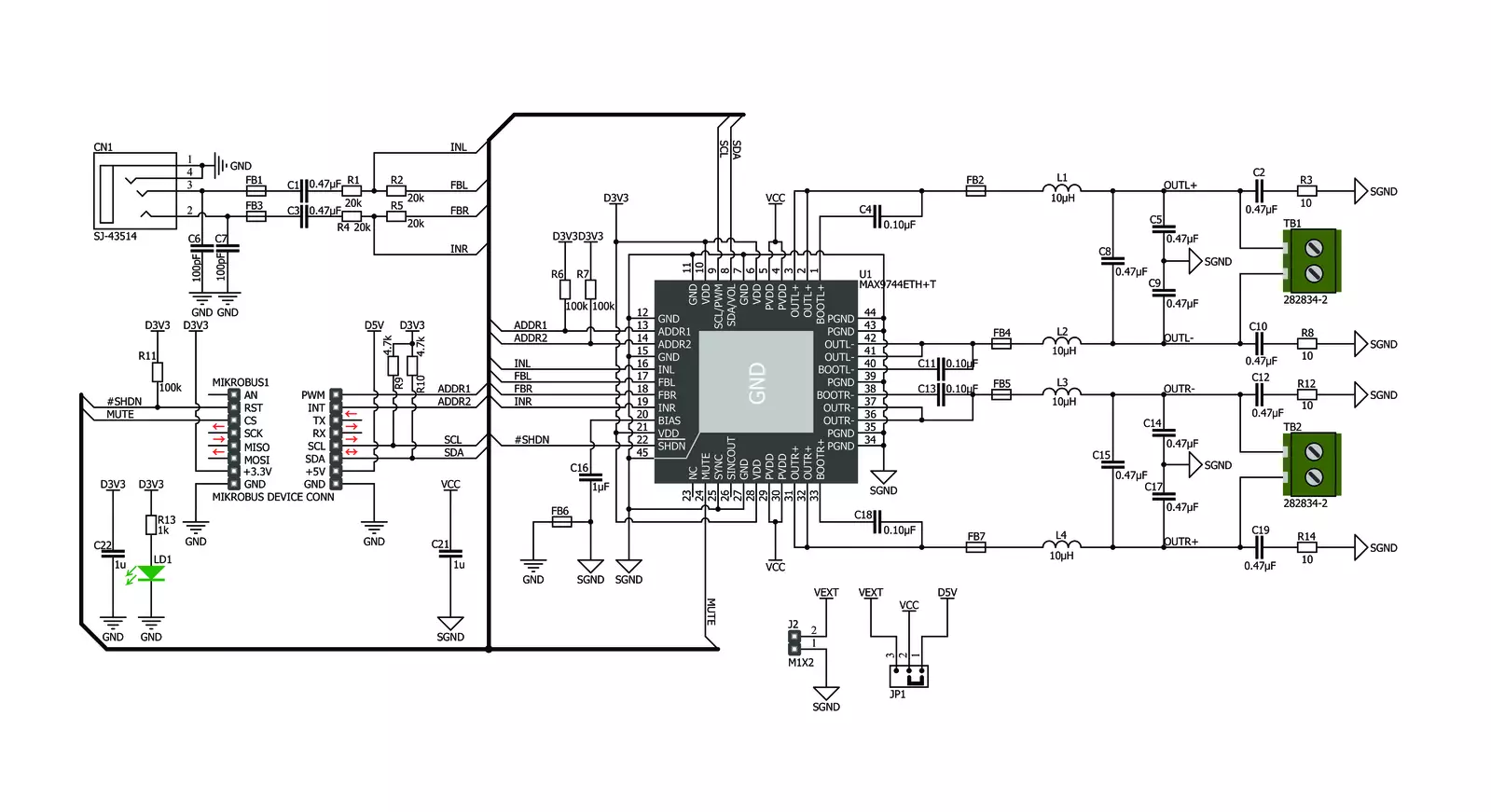
2x20W Amp Click is based on the MAX9744, a stereo class D audio power amplifier from Analog Devices. This click brings the Class AB sound performance with Class D efficiency, representing the perfect combination for your speakers. 2x20W Amp Click also offers 64-step volume control, single-supply operation, adjustable gain, and industry-leading click-and-pop suppression. Class-D amplifiers produce a series of square-shaped pulses of fixed amplitude but varying duty cycles, representing the amplitude variations of the analog signal. The output of the modulator is used to gate the output transistors on and off alternately. The high efficiency of a Class D amplifier is due to the switching operation of the output stage transistors. Since the transistors are either fully ON or fully OFF, they spend a small amount of time in the linear region and consume little power. In a Class D amplifier,
the output transistors act as current steering switches and don't use much additional power. A low-pass filter made of an inductor and a capacitor is used to produce a path for the low-frequencies of the audio signal (leaving the high-frequency pulses behind). When the output current exceeds the current limit, 5.5A (typ), the MAX9744 disables the outputs and initiates a 220µs startup sequence. The shutdown and startup sequence is repeated until the output fault is removed. When the die temperature exceeds the thermal-shutdown threshold, the MAX9744 outputs are disabled. The MAX9744 features a shutdown mode that reduces power consumption and extends battery life. Driving SHDN pin low places the device in low-power shutdown mode. Connect the SHDN pin to digital high for normal operation. The Click features volume control operation using an analog voltage input or
the I2C interface for maximum flexibility. To set the device to analog mode, connect ADDR1 and ADDR2 to GND. In analog mode, SDA/VOL pin is an analog input for volume control. The analog input range is ratiometric between 0.9 x VDD and 0.1 x VDD, where 0.9 x VDD = full mute and 0.1 x VDD = full volume. Use ADDR1 and ADDR2 to select I2C mode. Three addresses can be chosen, allowing multiple devices on a single bus. In the I2C mode, the volume is controlled by choosing the speaker volume control register in the command byte. There are 64 volume settings, where the lowest setting is full mute. The board logic is powered by the 3.3V supply over the mikroBUS™ socket, while the amplifier circuit is powered by the onboard 5V power supply or an external source that can go from 4.5V to 14V. The jumper JP1 must be positioned in the EXT position to use an external power source.

Features overview
Development board
PIC18F47K42 Curiosity Nano evaluation kit is a cutting-edge hardware platform designed to evaluate the PIC18F47K42 microcontroller (MCU). Central to its design is the inclusion of the powerful PIC18F47K42 microcontroller (MCU), offering advanced functionalities and robust performance. Key features of this evaluation kit include a yellow user LED and a responsive mechanical user switch
providing seamless interaction and testing. The provision for a 32.768kHz crystal footprint ensures precision timing capabilities. With an onboard debugger boasting a green power and status LED, programming and debugging become intuitive and efficient. Further enhancing its utility is the Virtual serial port (CDC) and a debug GPIO channel (DGI GPIO), offering extensive connectivity options.
Powered via USB, this kit boasts an adjustable target voltage feature facilitated by the MIC5353 LDO regulator, ensuring stable operation with an output voltage ranging from 2.3V to 5.1V (limited by USB input voltage), with a maximum output current of 500mA, subject to ambient temperature and voltage constraints.

Microcontroller Overview
MCU Card / MCU

Architecture
PIC
MCU Memory (KB)
128
Silicon Vendor
Microchip
Pin count
40
RAM (Bytes)
8192
You complete me!
Accessories
Curiosity Nano Base for Click boards is a versatile hardware extension platform created to streamline the integration between Curiosity Nano kits and extension boards, tailored explicitly for the mikroBUS™-standardized Click boards and Xplained Pro extension boards. This innovative base board (shield) offers seamless connectivity and expansion possibilities, simplifying experimentation and development. Key features include USB power compatibility from the Curiosity Nano kit, alongside an alternative external power input option for enhanced flexibility. The onboard Li-Ion/LiPo charger and management circuit ensure smooth operation for battery-powered applications, simplifying usage and management. Moreover, the base incorporates a fixed 3.3V PSU dedicated to target and mikroBUS™ power rails, alongside a fixed 5.0V boost converter catering to 5V power rails of mikroBUS™ sockets, providing stable power delivery for various connected devices.

Used MCU Pins
mikroBUS™ mapper
Take a closer look
Schematic
Step by step
Project assembly
Start by selecting your development board and Click board™. Begin with the Curiosity Nano with PIC18F47K42 as your development board.


Track your results in real time
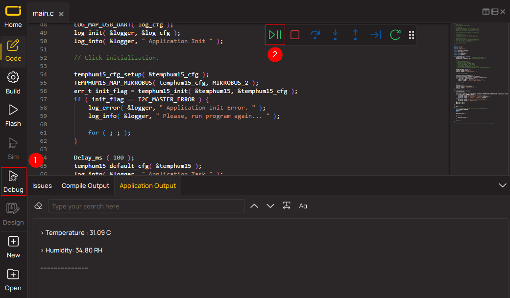
Application Output via Debug Mode
1. Once the code example is loaded, pressing the "DEBUG" button initiates the build process, programs it on the created setup, and enters Debug mode.
2. After the programming is completed, a header with buttons for various actions within the IDE becomes visible. Clicking the green "PLAY" button starts reading the results achieved with the Click board™. The achieved results are displayed in the Application Output tab.
Software Support
Library Description
This library contains API for 2x20W Amp Click driver.
Key functions:
c2x20wamp_mode_play- Set Play mode of the amplifier functionc2x20wamp_set_volume- Set volume of the amplifier functionc2x20wamp_mode_mute- Set Mute mode of the amplifier function
Open Source
Code example
This example can be found in NECTO Studio. Feel free to download the code, or you can copy the code below.
/*!
 * \file
 * \brief c2x20WAmp Click example
 *
 * # Description
 * This application changes the volume level.
 *
 * The demo application is composed of two sections :
 *
 * ## Application Init
 * Initialization driver enable's - I2C,
 * start write log and enable amplifire of 2x20W Amp Click board.
 *
 * ## Application Task
 * This is a example which demonstrates the use of 2x20W Amp Click board.
 * This examples first activates operation mode PLAY and set volume lvl 32,
 * after that, we increase the volume level one level ten times for 5 seconds
 * and  we decrease the volume level one level ten times for 5 seconds.
 * And finally, we set MUTE mode for next 5 seconds.
 * Results are being sent to the Usart Terminal
 * where you can track their changes.
 *
 * \author MikroE Team
 *
 */
// ------------------------------------------------------------------- INCLUDES

#include "board.h"
#include "log.h"
#include "c2x20wamp.h"

// ------------------------------------------------------------------ VARIABLES

static c2x20wamp_t c2x20wamp;
static log_t logger;

// ------------------------------------------------------ APPLICATION FUNCTIONS

void application_init ( void )
{
    log_cfg_t log_cfg;
    c2x20wamp_cfg_t cfg;

    /**
     * Logger initialization.
     * Default baud rate: 115200
     * Default log level: LOG_LEVEL_DEBUG
     * @note If USB_UART_RX and USB_UART_TX
     * are defined as HAL_PIN_NC, you will
     * need to define them manually for log to work.
     * See @b LOG_MAP_USB_UART macro definition for detailed explanation.
     */
    LOG_MAP_USB_UART( log_cfg );
    log_init( &logger, &log_cfg );
    log_info( &logger, "---- Application Init ----" );

    //  Click initialization.

    c2x20wamp_cfg_setup( &cfg );
    C2X20WAMP_MAP_MIKROBUS( cfg, MIKROBUS_1 );
    c2x20wamp_init( &c2x20wamp, &cfg );

    Delay_ms( 100 );

    log_printf( &logger, "-----------------------\r\n" );
    log_printf( &logger, "    2x20W Amp Click    \r\n" );
    log_printf( &logger, "-----------------------\r\n" );
    c2x20wamp_enable( &c2x20wamp );
    log_printf( &logger,"    Enable  Amplifier   \r\n" );
    log_printf( &logger, "-----------------------\r\n" );

    Delay_ms( 200 );
}

void application_task ( void )
{
    log_printf( &logger, "       PLAY MODE       \r\n" );
    c2x20wamp_mode_play( &c2x20wamp );
    Delay_ms( 200 );

    uint8_t volume = 32;

    log_printf( &logger, "  Set Volume lvl : %u  \r\n", (uint16_t)volume );
    log_printf( &logger, "-----------------------\r\n" );
    c2x20wamp_set_volume( &c2x20wamp, volume );

    log_printf( &logger, "- - - - - - - - - - - -\r\n" );

    Delay_ms( 5000 );

    for ( uint8_t cnt = 0; cnt < 10; cnt++ )
    {
        log_printf( &logger, "       Volume Up       \r\n" );

        c2x20wamp_volume_up( &c2x20wamp );

        Delay_ms( 100 );
    }

    log_printf( &logger, "- - - - - - - - - - - -\r\n" );

    Delay_ms( 5000 );

    for ( uint8_t cnt = 0; cnt < 10; cnt++ )
    {
        log_printf( &logger, "       Volume Down       \r\n" );

        c2x20wamp_volume_down( &c2x20wamp );

        Delay_ms( 100 );
    }

    log_printf( &logger, "-----------------------\r\n" );

    Delay_ms( 5000 );

    log_printf( &logger, "       MUTE MODE       \r\n" );

    c2x20wamp_mode_mute( &c2x20wamp );

    log_printf( &logger, "-----------------------\r\n" );

    Delay_ms( 5000 );
}

void main ( void )
{
    application_init( );

    for ( ; ; )
    {
        application_task( );
    }
}


// ------------------------------------------------------------------------ END


