Experience seamless and dynamic sound control with PT2258 and PIC32MZ2048EFM100
Unleash sonic perfection at your fingertips!

Published Dec 10, 2023
Click board™
EVC Click
Dev. board
Curiosity PIC32 MZ EF
Compiler
NECTO Studio
MCU
PIC32MZ2048EFM100
Discover a new level of audio quality and convenience with our six-channel digital volume controller, featuring an integrated electronic volume control circuit, designed to deliver sonic perfection with effortless control.
A
A
Hardware Overview
How does it work?
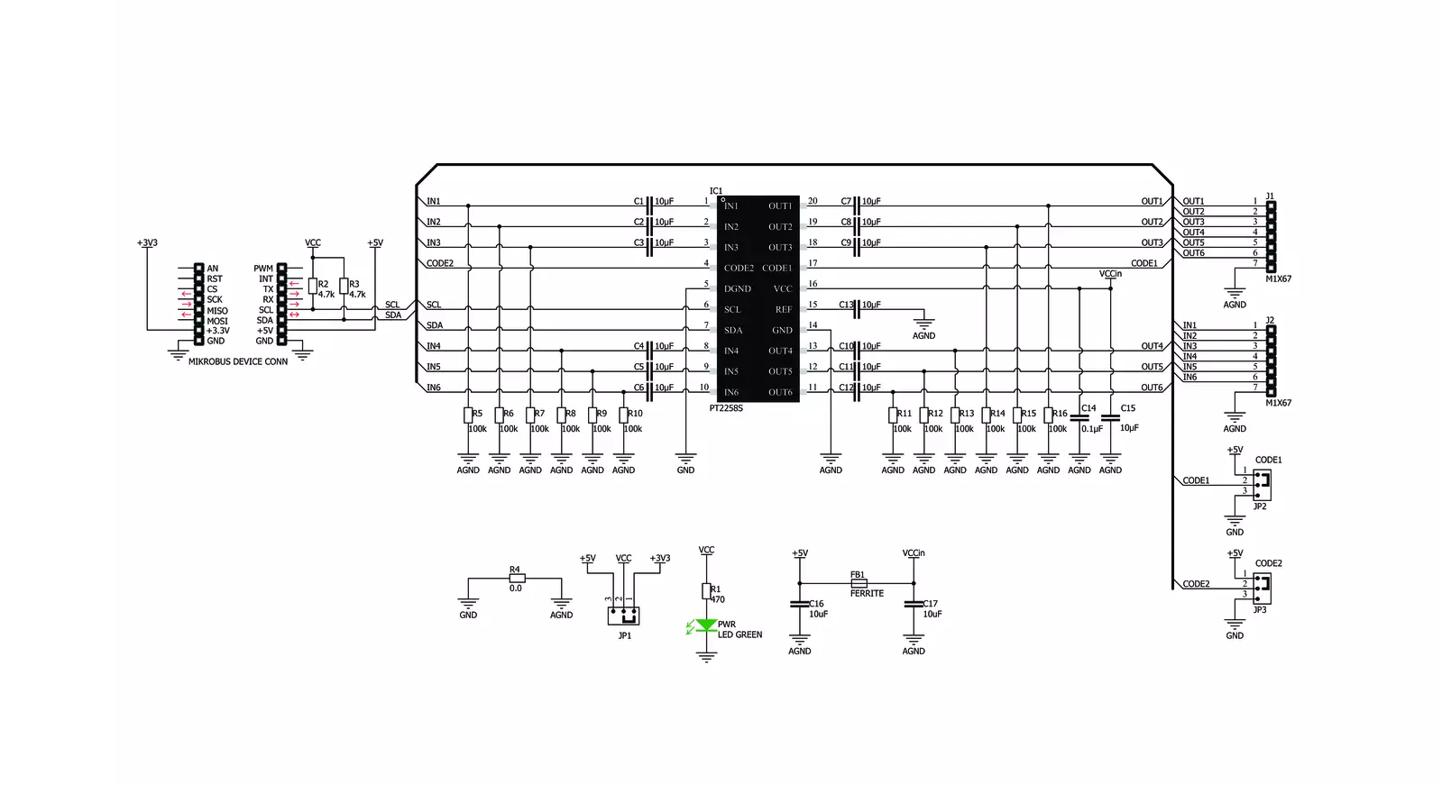
EVC Click is based on the PT2258, a six-channel electronic volume controller from Princeton Technology. This IC contains six digitally controlled audio attenuators, which can attenuate signals between 0dB and -79dB. Each channel can be individually controlled by two-byte commands, sent over the I2C interface. Although digitally controlled, sound signals within the PT2258 remain in the analog domain. The PT2258 offers a very clear and undistorted sound. The Signal to Noise Ratio (SNR) of the PT2258 is specified to be 105dB (1V RMS at any input), while the Total Harmonic Distortion (THD) is only 0.005% (200mV RMS at any input). THD gets worse as the input signal rises: 2.8V RMS results in THD of 1%. The maximum input signal should stay below 2.8V, else too much audible distortion may appear at the output. The Click board™ is equipped with two rows of standard 2.54mm (100 mil) headers. There are six pins at each row, allowing the inputs and the outputs to be easily interfaced with the existing multichannel equipment. This Click board™ should be connected on the signal path,
either in front of the amplifier itself, or in front or behind other sound processing equipment (e.g. equalizer, delay, room correction, and more). That way, an optimal audio signal level will be ensured for the Click board™. Each input/output pair runs through an internal attenuator, which provides up to -79dB of attenuation, in 1dB steps. Although it seems like a very high attenuation, using it with amplifiers with high gain values may lead to still hear the sound, even after the full attenuation. Therefore, the PT2258 features a MUTE function, that completely cuts the audio output. To set attenuation of a certain level, two bytes must be consequently sent over the I2C interface. There are both -1dB step commands and -10dB step commands for each channel. To achieve the desired attenuation at the specific channel, two commands should be sent consequently: one for -10 dB attenuation, and one for -1 dB attenuation. These commands can be sent in any order. However, sending a single command or adding a MUTE command between two attenuation commands may lead to unpredictable results. This Click
board™ is supported by a mikroSDK compliant library of functions, which greatly accelerate software development, by simplifying the software development. The I2C slave address of the Click board™ can be set using two SMD jumpers, grouped under the I2C ADD label. First SMD jumper is labeled as C1, while the second jumper is labeled as C2. These jumpers are used to configure bits CODE1 and CODE2, allowing several different I2C addresses to be selected. These jumpers can be independently moved to either position, allowing to select the desired slave address. Please refer to the PT2258 datasheet for more information about configuring the I2C slave address. The Click board™ uses the I2C interface for the communication. It can be interfaced with both 3.3V and 5V microcontrollers (MCUs) by simply switching the SMD jumper labeled as VCC COMM to a desired position. However, thePT2258 itself still requires 5V for its operation, since it requires a power supply voltage between 5V and 9V.

Features overview
Development board
Curiosity PIC32 MZ EF development board is a fully integrated 32-bit development platform featuring the high-performance PIC32MZ EF Series (PIC32MZ2048EFM) that has a 2MB Flash, 512KB RAM, integrated FPU, Crypto accelerator, and excellent connectivity options. It includes an integrated programmer and debugger, requiring no additional hardware. Users can expand
functionality through MIKROE mikroBUS™ Click™ adapter boards, add Ethernet connectivity with the Microchip PHY daughter board, add WiFi connectivity capability using the Microchip expansions boards, and add audio input and output capability with Microchip audio daughter boards. These boards are fully integrated into PIC32’s powerful software framework, MPLAB Harmony,
which provides a flexible and modular interface to application development a rich set of inter-operable software stacks (TCP-IP, USB), and easy-to-use features. The Curiosity PIC32 MZ EF development board offers expansion capabilities making it an excellent choice for a rapid prototyping board in Connectivity, IOT, and general-purpose applications.

Microcontroller Overview
MCU Card / MCU

Architecture
PIC32
MCU Memory (KB)
2048
Silicon Vendor
Microchip
Pin count
100
RAM (Bytes)
524288
Used MCU Pins
mikroBUS™ mapper
Take a closer look
Click board™ Schematic
Step by step
Project assembly

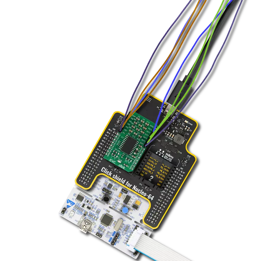
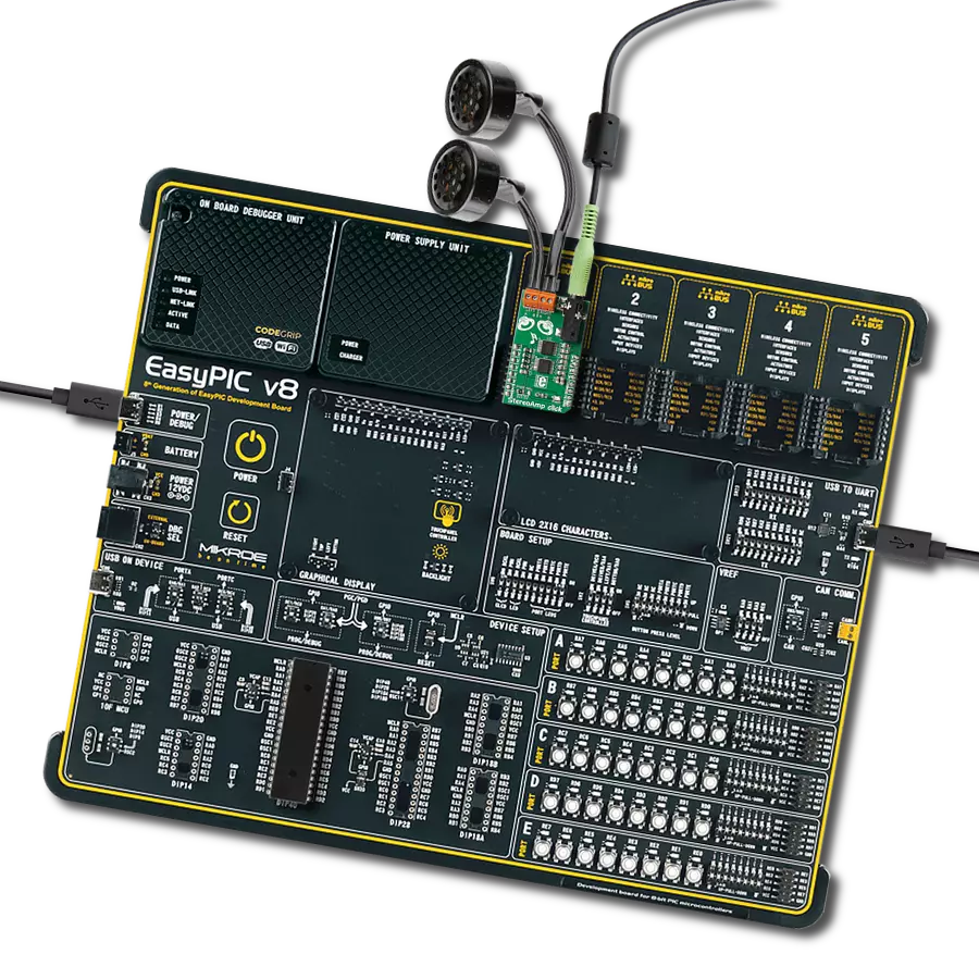
Start by selecting your development board and Click board™. Begin with the Curiosity PIC32 MZ EF as your development board.


Software Support
Library Description
This library contains API for EVC Click driver.
Key functions:
evc_set_volume_part- This function sets the volume for the selected channel, uses two variables.evc_set_volume_full- This function sets the volume for the selected channel, uses one volume variables.evc_mute- This function mute and unmute the sound.
Open Source
Code example
The complete application code and a ready-to-use project are available through the NECTO Studio Package Manager for direct installation in the NECTO Studio. The application code can also be found on the MIKROE GitHub account.
/*!
 * \file
 * \brief EVC Click example
 *
 * # Description
 * This application allows manipulation of 6 channel volume control
 *
 * The demo application is composed of two sections :
 *
 * ## Application Init
 * Initialization driver init, default configuration and sets first volume.
 *
 * ## Application Task
 * emulates user input and exectuyrd functions based on set of valid commands.
 *
 * *note:*
 * Additional Functions :
 *
 * void test_change ( )               - Emulates user input to change parameters.
 * void mute( )                       - Mute nad
 * void play ( )                      - Start new settings of the cahnnel
 * uint8_t get_current_channel ( )    - Return current channel.
 *
 * \author MikroE Team
 *
 */
// ------------------------------------------------------------------- INCLUDES

#include "board.h"
#include "log.h"
#include "evc.h"

// ------------------------------------------------------------------ VARIABLES

static evc_t evc;
static log_t logger;

// ------------------------------------------------------- ADDITIONAL FUNCTIONS

uint8_t get_current_channel ( uint8_t ch )
{
    if ( ch == 1 )
    {
        return EVC_CHANNEL_1;
    }
    if ( ch == 2 )
    {
        return EVC_CHANNEL_2;
    }
    if ( ch == 3 )
    {
        return EVC_CHANNEL_3;
    }
    if ( ch == 4 )
    {
        return EVC_CHANNEL_4;
    }
    if ( ch == 5 )
    {
        return EVC_CHANNEL_5;
    }
    if ( ch == 6 )
    {
        return EVC_CHANNEL_6;
    }
    return EVC_CHANNEL_1;
}

void play ( evc_t *ctx )
{
    uint8_t current_channel;

    if ( ( ctx->play_flag == 1 ) && ( ctx->mute_flag != 1 ) )
    {
        current_channel = get_current_channel( ctx->channel );
        evc_set_volume_full( ctx, current_channel, ctx->volume );

        log_printf( &logger, " Channel [ %d ] -- Volume [ %d ] \r\n", ctx->channel, ctx->volume );

        ctx->play_flag = 0;
    }
}

void mute( evc_t *ctx )
{
    /* Mute and Unmute */
    if ( ctx->mute_flag == 0 )
    {
        ctx->mute_flag = 1;
        evc_mute( ctx, EVC_ALL_CHANNEL_MUTE );
        log_printf( &logger, " All channels MUTE !!!\r\n" );
    }
    else
    {
        ctx->mute_flag = 0;
        evc_mute( ctx, EVC_ALL_CHANNEL_UNMUTE );
        log_printf( &logger, " All channels UNMUTE !!!\r\n" );
    }
}

void test_change ( evc_t *ctx )
{
    ctx->channel++;

    if( ctx->channel > 6 )
    {
        ctx->channel = 6;
    }

    ctx->volume--;
    if( ctx->volume < -79 )
    {
        ctx->volume = -79;
        mute( ctx );
    }

    ctx->play_flag = 1;

    Delay_ms ( 750 );

}

// ------------------------------------------------------ APPLICATION FUNCTIONS

void application_init ( void )
{
    log_cfg_t log_cfg;
    evc_cfg_t cfg;

    /**
     * Logger initialization.
     * Default baud rate: 115200
     * Default log level: LOG_LEVEL_DEBUG
     * @note If USB_UART_RX and USB_UART_TX
     * are defined as HAL_PIN_NC, you will
     * need to define them manually for log to work.
     * See @b LOG_MAP_USB_UART macro definition for detailed explanation.
     */
    LOG_MAP_USB_UART( log_cfg );
    log_init( &logger, &log_cfg );
    log_info( &logger, "---- Application Init ----" );

    //  Click initialization.

    evc_cfg_setup( &cfg );
    EVC_MAP_MIKROBUS( cfg, MIKROBUS_1 );
    evc_init( &evc, &cfg );

    evc_default_cfg( &evc );
    log_printf( &logger, " \\-/-\\-/ START EQUALIZER \\-/-\\-/ ");
}

void application_task ( void )
{
    //  Task implementation.

    test_change( &evc );

    play( &evc );
}

int main ( void )
{
    /* Do not remove this line or clock might not be set correctly. */
    #ifdef PREINIT_SUPPORTED
    preinit();
    #endif

    application_init( );

    for ( ; ; )
    {
        application_task( );
    }

    return 0;
}


// ------------------------------------------------------------------------ END
Additional Support
Resources
Category:Amplifier