Accurately detect the presence of alcohol vapors with MQ-3 and ATmega328
Breathe, test, and stay safe!

Published Feb 14, 2024
Click board™
Alcohol Click
Dev. board
Arduino UNO Rev3
Compiler
NECTO Studio
MCU
ATmega328
Develop innovative solutions that feature advanced ethanol gas detection technology
A
A
Hardware Overview
How does it work?
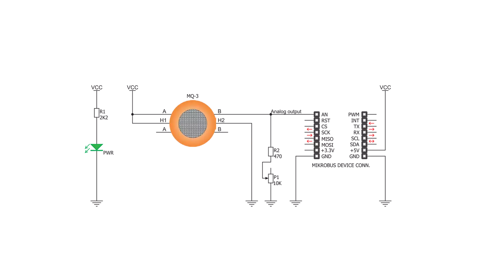
Alcohol Click is based on the MQ-3, an alcohol sensor module from Zhengzhou Winsen Electronics Technology, which detects the presence and concentration of alcohol in the air. The MQ-3 gas sensor comprises a micro AL2O3 ceramic tube, a Tin Dioxide (SnO2) sensitive layer, a measuring electrode, and a heater fixed into a plastic and stainless steel net crust. The heater provides necessary work conditions for the work of sensitive components. It has a high sensitivity to alcohol and
slight to benzine, suitable for detecting alcohol in concentrations from 0.04 to 4mg/l. The MQ-3 provides an analog representation of its concentration in the air sent directly to an analog pin of the mikroBUS™ socket labeled OUT. The analog output voltage the sensor provides varies in proportion to the alcohol concentration; the higher the alcohol concentration in the air, the higher the output voltage. Also, this Click board™ has a built-in potentiometer that allows users to adjust the
Load Resistance of the MQ-3 circuit for optimum performance. This Click board™ can only be operated with a 5V logic voltage level. The board must perform appropriate logic voltage level conversion before using MCUs with different logic levels. However, the Click board™ comes equipped with a library containing functions and an example code that can be used, as a reference, for further development.

Features overview
Development board
Arduino UNO is a versatile microcontroller board built around the ATmega328P chip. It offers extensive connectivity options for various projects, featuring 14 digital input/output pins, six of which are PWM-capable, along with six analog inputs. Its core components include a 16MHz ceramic resonator, a USB connection, a power jack, an
ICSP header, and a reset button, providing everything necessary to power and program the board. The Uno is ready to go, whether connected to a computer via USB or powered by an AC-to-DC adapter or battery. As the first USB Arduino board, it serves as the benchmark for the Arduino platform, with "Uno" symbolizing its status as the
first in a series. This name choice, meaning "one" in Italian, commemorates the launch of Arduino Software (IDE) 1.0. Initially introduced alongside version 1.0 of the Arduino Software (IDE), the Uno has since become the foundational model for subsequent Arduino releases, embodying the platform's evolution.

Microcontroller Overview
MCU Card / MCU

Architecture
AVR
MCU Memory (KB)
32
Silicon Vendor
Microchip
Pin count
32
RAM (Bytes)
2048
You complete me!
Accessories
Click Shield for Arduino UNO has two proprietary mikroBUS™ sockets, allowing all the Click board™ devices to be interfaced with the Arduino UNO board without effort. The Arduino Uno, a microcontroller board based on the ATmega328P, provides an affordable and flexible way for users to try out new concepts and build prototypes with the ATmega328P microcontroller from various combinations of performance, power consumption, and features. The Arduino Uno has 14 digital input/output pins (of which six can be used as PWM outputs), six analog inputs, a 16 MHz ceramic resonator (CSTCE16M0V53-R0), a USB connection, a power jack, an ICSP header, and reset button. Most of the ATmega328P microcontroller pins are brought to the IO pins on the left and right edge of the board, which are then connected to two existing mikroBUS™ sockets. This Click Shield also has several switches that perform functions such as selecting the logic levels of analog signals on mikroBUS™ sockets and selecting logic voltage levels of the mikroBUS™ sockets themselves. Besides, the user is offered the possibility of using any Click board™ with the help of existing bidirectional level-shifting voltage translators, regardless of whether the Click board™ operates at a 3.3V or 5V logic voltage level. Once you connect the Arduino UNO board with our Click Shield for Arduino UNO, you can access hundreds of Click boards™, working with 3.3V or 5V logic voltage levels.

Used MCU Pins
mikroBUS™ mapper
Take a closer look
Click board™ Schematic
Step by step
Project assembly

Start by selecting your development board and Click board™. Begin with the Arduino UNO Rev3 as your development board.


Software Support
Library Description
This library contains API for Alcohol Click driver.
Key functions:
alcohol_read_an_pin_value - This function reads results of AD conversion of the AN pin.
alcohol_read_an_pin_voltage - This function reads results of AD conversion of the AN pin and converts them to proportional voltage level.
Open Source
Code example
The complete application code and a ready-to-use project are available through the NECTO Studio Package Manager for direct installation in the NECTO Studio. The application code can also be found on the MIKROE GitHub account.
/*!
 * @file main.c
 * @brief Alcohol Click Example.
 *
 * # Description
 * The demo application shows the reading of the adc
 * values given by the sensors.
 *
 * The demo application is composed of two sections :
 *
 * ## Application Init
 * Configuring Clicks and log objects.
 *
 * ## Application Task
 * Reads the adc value and prints in two forms (DEC and HEX).
 *
 * @author Jelena Milosavljevic
 *
 */

#include "board.h"
#include "log.h"
#include "alcohol.h"

static alcohol_t alcohol;   /**< Alcohol Click driver object. */
static log_t logger;    /**< Logger object. */

void application_init ( void ) {
    log_cfg_t log_cfg;  /**< Logger config object. */
    alcohol_cfg_t alcohol_cfg;  /**< Click config object. */

    /**
     * Logger initialization.
     * Default baud rate: 115200
     * Default log level: LOG_LEVEL_DEBUG
     * @note If USB_UART_RX and USB_UART_TX
     * are defined as HAL_PIN_NC, you will
     * need to define them manually for log to work.
     * See @b LOG_MAP_USB_UART macro definition for detailed explanation.
     */
    LOG_MAP_USB_UART( log_cfg );
    log_init( &logger, &log_cfg );
    log_info( &logger, " Application Init " );

    // Click initialization.

    alcohol_cfg_setup( &alcohol_cfg );
    ALCOHOL_MAP_MIKROBUS( alcohol_cfg, MIKROBUS_1 );
    if ( alcohol_init( &alcohol, &alcohol_cfg ) == ADC_ERROR ) {
        log_error( &logger, " Application Init Error. " );
        log_info( &logger, " Please, run program again... " );

        for ( ; ; );
    }
    log_info( &logger, " Application Task " );
    Delay_ms ( 100 );
}

void application_task ( void ) {
    uint16_t alcohol_an_value = 0;

    if ( alcohol_read_an_pin_value ( &alcohol, &alcohol_an_value ) != ADC_ERROR ) {
        log_printf( &logger, " ADC Value : %u\r\n", alcohol_an_value );
    }

    float alcohol_an_voltage = 0;

    if ( alcohol_read_an_pin_voltage ( &alcohol, &alcohol_an_voltage ) != ADC_ERROR ) {
        log_printf( &logger, " AN Voltage : %.3f[V]\r\n\n", alcohol_an_voltage );
    }

    Delay_ms ( 1000 );
}

int main ( void )
{
    /* Do not remove this line or clock might not be set correctly. */
    #ifdef PREINIT_SUPPORTED
    preinit();
    #endif

    application_init( );

    for ( ; ; )
    {
        application_task( );
    }

    return 0;
}

// ------------------------------------------------------------------------ END
Additional Support
Resources
Category:Gas


