Capture, track, and manage information with ease using LV3296 and ATmega328P
Streamline inventory management with precision

Published Feb 14, 2024
Click board™
Barcode Click
Dev. board
Arduino UNO Rev3
Compiler
NECTO Studio
MCU
ATmega328P
The purpose of this scanner is to enhance retail efficiency by quickly and accurately capturing product information
A
A
Hardware Overview
How does it work?
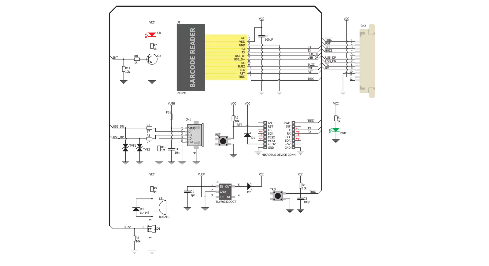
Barcode Click is based on the LV3296 from Rakinda. This is the advanced barcode scanner/reader module which features the patented UIMG®, a computerized image recognition system technology that supports all mainstream 1D and standard 2D barcode types (for example - PDF417, QR Code M1/M2/Micro and Data Matrix) as well as GS1-DataBar™(RSS) (Limited/Stacked/Expanded versions). It can read barcodes on virtually any medium, including paper, plastic, mobile phones, LCD displays, etc. Thanks to the used area-imaging and UIMG® technologies, the device is able to scan barcodes rotated to any angle, with great speed and precision. The LV3296 scanner module uses a flat cable to connect to the click board™, via the ZIF FPC connector on the back side of the PCB. This flat cable carries all the signals used in communication between the LV3296 module and the host MCU, such as the RX, TX, buzzer, USB, interrupt, reset, and scanning trigger lines. The communication with Barcode click is done by utilizing two types of connection it offers - UART (TTL232) and USB. When the click board™ is placed into the mikroBUS™ socket, it will be able to exchange data with the UART module of the
MCU, via the standard mikroBUS™ RX and TX pins. When the USB cable is connected to the micro USB port on the click board itself, it can be identified either as the virtual USB port, a HID keyboard device or an HID POS device. HID devices do not require any special PC drivers, while the virtual USB device does. Many options and parameters of the Barcode click are configurable. Barcode click configuration is very easy and intuitive - it is enough to read special configuration messages, encoded into barcodes that can be found in the LV3296 user's guide. It is not even necessary to print them on paper - it is enough to show them on screen and scan them from there. Enter Setup message should be scanned first, followed by the desired configuration message. After successful configuration indicated by a short beep sound, the Exit Setup message should be scanned. The device features a very extensive set of encoded configuration commands, which include storing and recal of user default values, along with the factory defaults. When the Barcode device is first powered up, it will sound a greeting message, which indicates the successful initialization. The device is now ready to scan. Pressing the onboard TRIG button or pulling the
PWM pin of the mikroBUS™ slot to a LOW logic level for at least 10ms, will trigger the barcode scan. It will turn on two LEDs and project a circle shaped aiming pattern on the surface it is aimed at, scanning it for a valid barcode. Both LEDs and the aiming pattern can be turned off in the configuration. A short beep sound and a blink of the Good Read indication onboard LED (GR) will indicate a successful barcode decoding and after releasing the TRIG line (configurable), the device will send the decoded information to the selected interface. Barcode click can report errors, with a distinctive error message sound - e.g. when the device is configured to use onboard micro USB, but it is not connected to the host USB device, it will sound an error if scanning is attempted. The RST button is used to reset the device. Pressing the RST button or pulling the RST line, routed to the mikroBUS™ RST pin to a LOW logic level for 100us to 500us will cause a device reset, followed by the greeting message sound. It should be noted that the device should not be reset too frequently; at least 2 seconds delay should exist between the reset cycles.

Features overview
Development board
Arduino UNO is a versatile microcontroller board built around the ATmega328P chip. It offers extensive connectivity options for various projects, featuring 14 digital input/output pins, six of which are PWM-capable, along with six analog inputs. Its core components include a 16MHz ceramic resonator, a USB connection, a power jack, an
ICSP header, and a reset button, providing everything necessary to power and program the board. The Uno is ready to go, whether connected to a computer via USB or powered by an AC-to-DC adapter or battery. As the first USB Arduino board, it serves as the benchmark for the Arduino platform, with "Uno" symbolizing its status as the
first in a series. This name choice, meaning "one" in Italian, commemorates the launch of Arduino Software (IDE) 1.0. Initially introduced alongside version 1.0 of the Arduino Software (IDE), the Uno has since become the foundational model for subsequent Arduino releases, embodying the platform's evolution.

Microcontroller Overview
MCU Card / MCU

Architecture
AVR
MCU Memory (KB)
32
Silicon Vendor
Microchip
Pin count
28
RAM (Bytes)
2048
You complete me!
Accessories
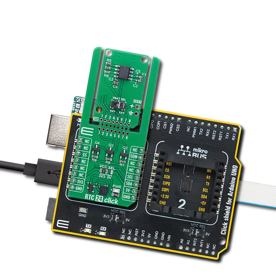
Click Shield for Arduino UNO has two proprietary mikroBUS™ sockets, allowing all the Click board™ devices to be interfaced with the Arduino UNO board without effort. The Arduino Uno, a microcontroller board based on the ATmega328P, provides an affordable and flexible way for users to try out new concepts and build prototypes with the ATmega328P microcontroller from various combinations of performance, power consumption, and features. The Arduino Uno has 14 digital input/output pins (of which six can be used as PWM outputs), six analog inputs, a 16 MHz ceramic resonator (CSTCE16M0V53-R0), a USB connection, a power jack, an ICSP header, and reset button. Most of the ATmega328P microcontroller pins are brought to the IO pins on the left and right edge of the board, which are then connected to two existing mikroBUS™ sockets. This Click Shield also has several switches that perform functions such as selecting the logic levels of analog signals on mikroBUS™ sockets and selecting logic voltage levels of the mikroBUS™ sockets themselves. Besides, the user is offered the possibility of using any Click board™ with the help of existing bidirectional level-shifting voltage translators, regardless of whether the Click board™ operates at a 3.3V or 5V logic voltage level. Once you connect the Arduino UNO board with our Click Shield for Arduino UNO, you can access hundreds of Click boards™, working with 3.3V or 5V logic voltage levels.

Used MCU Pins
mikroBUS™ mapper
Take a closer look
Click board™ Schematic
Step by step
Project assembly

Start by selecting your development board and Click board™. Begin with the Arduino UNO Rev3 as your development board.


Software Support
Library Description
This library contains API for Barcode Click driver.
Key functions:
barcode_enable_scaning- Set PWM pin statebarcode_generic_read- Generic read function.
Open Source
Code example
The complete application code and a ready-to-use project are available through the NECTO Studio Package Manager for direct installation in the NECTO Studio. The application code can also be found on the MIKROE GitHub account.
/*!
 * \file
 * \brief Barcode Click example
 *
 * # Description
 * This example reads and processes data from Barcode Clicks.
 *
 * The demo application is composed of two sections :
 *
 * ## Application Init
 * Initializes driver.
 *
 * ## Application Task
 * Reads the received data.
 *
 * ## Additional Function
 * - barcode_process( ) - The general process of collecting presponce
 *                                   that sends a module.
 *
 * \author Nemanja Medakovic
 *
 */
// ------------------------------------------------------------------- INCLUDES

#include "board.h"
#include "log.h"
#include "barcode.h"
#include "string.h"

#define PROCESS_COUNTER 2000
#define PROCESS_RX_BUFFER_SIZE 300

// ------------------------------------------------------------------ VARIABLES

static barcode_t barcode;
static log_t logger;

// ------------------------------------------------------- ADDITIONAL FUNCTIONS

static void barcode_process ( void )
{
    uint16_t rsp_size;
    uint16_t rsp_cnt = 0;

    char uart_rx_buffer[ PROCESS_RX_BUFFER_SIZE ] = { 0 };
    uint16_t check_buf_cnt;
    uint16_t process_cnt = PROCESS_COUNTER;

    while( process_cnt > 0 )
    {
        rsp_size = barcode_generic_read( &barcode, &uart_rx_buffer, PROCESS_RX_BUFFER_SIZE );

        if ( rsp_size > 0 )
        {
            // Validation of the received data
            for ( check_buf_cnt = 0; check_buf_cnt < rsp_size; check_buf_cnt++ )
            {
                if ( uart_rx_buffer[ check_buf_cnt ] == 0 )
                {
                    uart_rx_buffer[ check_buf_cnt ] = 13;
                }
            }

            log_printf( &logger, "%s", uart_rx_buffer );

            // Clear RX buffer
            memset( uart_rx_buffer, 0, PROCESS_RX_BUFFER_SIZE );
        }
        else
        {
            process_cnt--;

            // Process delay
            Delay_ms ( 1 );
        }
    }
}

// ------------------------------------------------------ APPLICATION FUNCTIONS

void application_init ( void )
{
    log_cfg_t log_cfg;
    barcode_cfg_t cfg;

    /**
     * Logger initialization.
     * Default baud rate: 115200
     * Default log level: LOG_LEVEL_DEBUG
     * @note If USB_UART_RX and USB_UART_TX
     * are defined as HAL_PIN_NC, you will
     * need to define them manually for log to work.
     * See @b LOG_MAP_USB_UART macro definition for detailed explanation.
     */
    LOG_MAP_USB_UART( log_cfg );
    log_init( &logger, &log_cfg );
    log_info( &logger, "--->  BarCode Click Init  <---" );

    //  Click initialization.

    barcode_cfg_setup( &cfg );
    BARCODE_MAP_MIKROBUS( cfg, MIKROBUS_1 );
    barcode_init( &barcode, &cfg );

    Delay_ms ( 500 );
}

void application_task ( void )
{
    barcode_enable_scaning( &barcode, BARCODE_LOGIC_ON );
    barcode_process( );
    barcode_enable_scaning( &barcode, BARCODE_LOGIC_OFF );
    Delay_ms ( 1000 );
    Delay_ms ( 1000 );
}

int main ( void )
{
    /* Do not remove this line or clock might not be set correctly. */
    #ifdef PREINIT_SUPPORTED
    preinit();
    #endif

    application_init( );

    for ( ; ; )
    {
        application_task( );
    }

    return 0;
}

// ------------------------------------------------------------------------ END
Additional Support
Resources
Category:Miscellaneous