Tailor-made Bluetooth solution with WT41u and ATmega328P
Wireless wonders at your fingertips

Published Feb 14, 2024
Click board™
Bluetooth 2 Click
Dev. board
Arduino UNO Rev3
Compiler
NECTO Studio
MCU
ATmega328P
Ready to revolutionize your automotive diagnostics unit? Add this Bluetooth solution now!
A
A
Hardware Overview
How does it work?
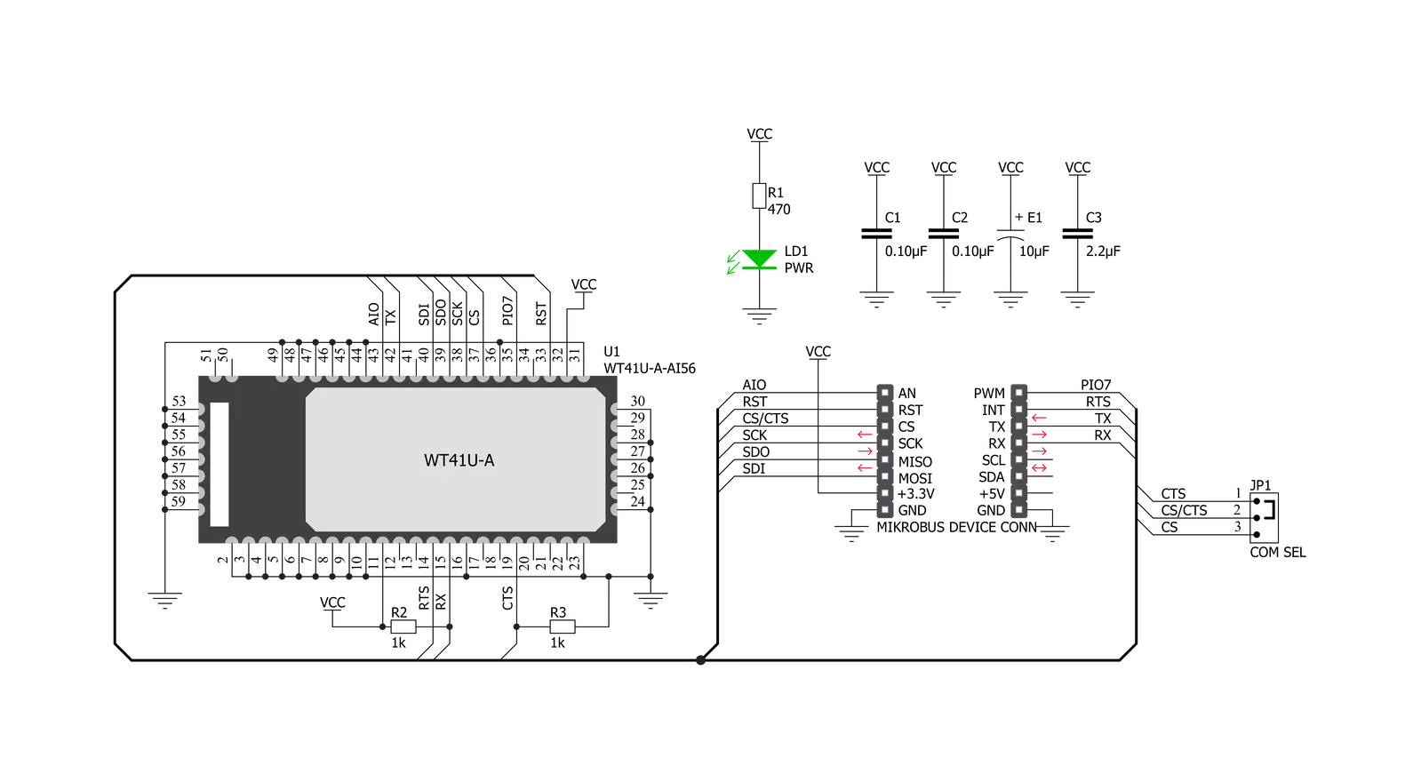
Bluetooth 2 Click is based on the WT41u, a fully integrated Bluetooth 2.1 + EDR, Class 1 module from Silicon Labs. Combining an onboard chip antenna, Bluetooth radio, and an onboard iWRAP Bluetooth Stack, the WT41u provides a superior link budget and 650-meter line-of-sight connectivity for Bluetooth applications with extreme radio performance or required reliability. Thanks to Bluegiga's iWRAP Bluetooth stack, the WT41u implements 13 different Bluetooth profiles and Apple iAP connectivity ensuring quick time-to-market. This Click board™ represents an ideal solution for rapidly integrating high-performing Bluetooth wireless technology without investing
several months in Bluetooth radio and stack development. The WT41u communicates with MCU using the UART interface, RS232 protocol, with commonly used UART RX, TX, and hardware flow control pins UART CTS and RTS. The UART configuration parameters, such as data rate and packet format, are set using WT41u software. In addition to the UART interface, an SPI interface is available, but only for system debugging. The WT41u uses 16-bit data and a 16-bit address serial peripheral interface to program the Flash memory and set the PSKEY configurations. The CS pin has a dual function, as the CS pin of the SPI interface or CTS for UART, can be
selected by moving the SMD jumper designated as COM SEL to an appropriate position. Besides the commonly used interface pins, Bluetooth 2 Click also has a general reset and bidirectional digital/analog I/O pins routed to the RST, PWM, and AN pins of the mikroBUS™ socket, respectively. This Click board™ can be operated only with a 3.3V logic voltage level. The board must perform appropriate logic voltage level conversion before using MCUs with different logic levels. However, the Click board™ comes equipped with a library containing functions and an example code that can be used, as a reference, for further development.


Features overview
Development board
Arduino UNO is a versatile microcontroller board built around the ATmega328P chip. It offers extensive connectivity options for various projects, featuring 14 digital input/output pins, six of which are PWM-capable, along with six analog inputs. Its core components include a 16MHz ceramic resonator, a USB connection, a power jack, an
ICSP header, and a reset button, providing everything necessary to power and program the board. The Uno is ready to go, whether connected to a computer via USB or powered by an AC-to-DC adapter or battery. As the first USB Arduino board, it serves as the benchmark for the Arduino platform, with "Uno" symbolizing its status as the
first in a series. This name choice, meaning "one" in Italian, commemorates the launch of Arduino Software (IDE) 1.0. Initially introduced alongside version 1.0 of the Arduino Software (IDE), the Uno has since become the foundational model for subsequent Arduino releases, embodying the platform's evolution.

Microcontroller Overview
MCU Card / MCU

Architecture
AVR
MCU Memory (KB)
32
Silicon Vendor
Microchip
Pin count
28
RAM (Bytes)
2048
You complete me!
Accessories
Click Shield for Arduino UNO has two proprietary mikroBUS™ sockets, allowing all the Click board™ devices to be interfaced with the Arduino UNO board without effort. The Arduino Uno, a microcontroller board based on the ATmega328P, provides an affordable and flexible way for users to try out new concepts and build prototypes with the ATmega328P microcontroller from various combinations of performance, power consumption, and features. The Arduino Uno has 14 digital input/output pins (of which six can be used as PWM outputs), six analog inputs, a 16 MHz ceramic resonator (CSTCE16M0V53-R0), a USB connection, a power jack, an ICSP header, and reset button. Most of the ATmega328P microcontroller pins are brought to the IO pins on the left and right edge of the board, which are then connected to two existing mikroBUS™ sockets. This Click Shield also has several switches that perform functions such as selecting the logic levels of analog signals on mikroBUS™ sockets and selecting logic voltage levels of the mikroBUS™ sockets themselves. Besides, the user is offered the possibility of using any Click board™ with the help of existing bidirectional level-shifting voltage translators, regardless of whether the Click board™ operates at a 3.3V or 5V logic voltage level. Once you connect the Arduino UNO board with our Click Shield for Arduino UNO, you can access hundreds of Click boards™, working with 3.3V or 5V logic voltage levels.

Used MCU Pins
mikroBUS™ mapper
Take a closer look
Click board™ Schematic
Step by step
Project assembly

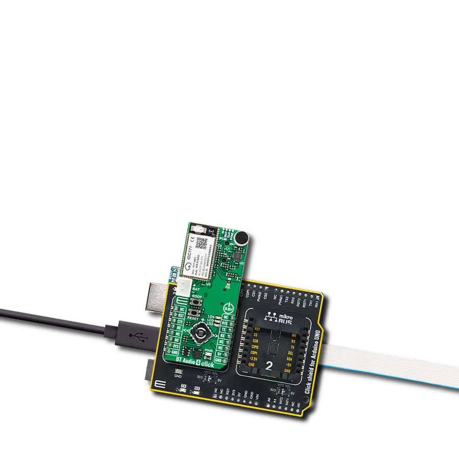
Start by selecting your development board and Click board™. Begin with the Arduino UNO Rev3 as your development board.


Track your results in real time
Application Output
1. Application Output - In Debug mode, the 'Application Output' window enables real-time data monitoring, offering direct insight into execution results. Ensure proper data display by configuring the environment correctly using the provided tutorial.

2. UART Terminal - Use the UART Terminal to monitor data transmission via a USB to UART converter, allowing direct communication between the Click board™ and your development system. Configure the baud rate and other serial settings according to your project's requirements to ensure proper functionality. For step-by-step setup instructions, refer to the provided tutorial.

3. Plot Output - The Plot feature offers a powerful way to visualize real-time sensor data, enabling trend analysis, debugging, and comparison of multiple data points. To set it up correctly, follow the provided tutorial, which includes a step-by-step example of using the Plot feature to display Click board™ readings. To use the Plot feature in your code, use the function: plot(*insert_graph_name*, variable_name);. This is a general format, and it is up to the user to replace 'insert_graph_name' with the actual graph name and 'variable_name' with the parameter to be displayed.

Software Support
Library Description
This library contains API for Bluetooth 2 Click driver.
Key functions:
bluetooth2_factory_reset- This function factory resets the devicebluetooth2_set_device_name- This function sets the local device namebluetooth2_generic_write- This function writes a desired number of data bytes by using UART serial interface
Open Source
Code example
The complete application code and a ready-to-use project are available through the NECTO Studio Package Manager for direct installation in the NECTO Studio. The application code can also be found on the MIKROE GitHub account.
/*!
 * @file main.c
 * @brief Bluetooth 2 Click Example.
 *
 * # Description
 * This example reads and processes data from Bluetooth 2 Clicks.
 *
 * The demo application is composed of two sections :
 *
 * ## Application Init
 * Initializes the driver, then performs a factory reset, removes all pairings, and
 * sets the local device name.
 *
 * ## Application Task
 * Logs all the received messages/responses on the USB UART, and if there's any device
 * connected to the Click board the module sends a desired message every 5 seconds back to it.
 *
 * ## Additional Function
 * - static void bluetooth2_clear_app_buf ( void )
 * - static err_t bluetooth2_process ( void )
 * - static err_t bluetooth2_display_rsp ( uint16_t timeout )
 *
 * @note
 * We have used the Serial Bluetooth Terminal smartphone application for the test.
 * A smartphone and the Click board must be paired in order to exchange messages with each other.
 *
 * @author Stefan Filipovic
 *
 */

#include "board.h"
#include "log.h"
#include "bluetooth2.h"

#define PROCESS_BUFFER_SIZE 200

#define RSP_OK              "OK."
#define RSP_READY           "READY."
#define RSP_RING            "RING"
#define RSP_NO_CARRIER      "NO CARRIER"

// Local device name.
#define DEVICE_NAME         "Bluetooth 2 Click"

// Message which will be sent to the connected device.
#define TEXT_TO_SEND        "MikroE - Bluetooth 2 Click\r\n"

// Text sending frequency in miliseconds.
#define SENDING_FREQ        5000

static bluetooth2_t bluetooth2;
static log_t logger;

static char app_buf[ PROCESS_BUFFER_SIZE ] = { 0 };
static int32_t app_buf_len = 0;
static int32_t app_buf_cnt = 0;
static uint8_t connection_flag = 0;
static uint16_t send_cnt = 0;

/**
 * @brief Bluetooth 2 clearing application buffer.
 * @details This function clears memory of application buffer and reset its length and counter.
 * @note None.
 */
static void bluetooth2_clear_app_buf ( void );

/**
 * @brief Bluetooth 2 data reading function.
 * @details This function reads data from device and concatenates data to application buffer.
 *
 * @return @li @c  0 - Read some data.
 *         @li @c -1 - Nothing is read.
 *         @li @c -2 - Application buffer overflow.
 *
 * See #err_t definition for detailed explanation.
 * @note None.
 */
static err_t bluetooth2_process ( void );

/**
 * @brief Bluetooth 2 display response function.
 * @details This function reads data from device until it sends OK or READY message or until
 * it exceeds the timeout value.
 * @param[in] timeout : Timeout value in miliseconds.
 *
 * @return @li @c  0 - Read some data.
 *         @li @c -1 - Nothing is read.
 *
 * See #err_t definition for detailed explanation.
 * @note None.
 */
static err_t bluetooth2_display_rsp ( uint16_t timeout );

void application_init ( void )
{
    log_cfg_t log_cfg;                /**< Logger config object. */
    bluetooth2_cfg_t bluetooth2_cfg;  /**< Click config object. */

    /**
     * Logger initialization.
     * Default baud rate: 115200
     * Default log level: LOG_LEVEL_DEBUG
     * @note If USB_UART_RX and USB_UART_TX
     * are defined as HAL_PIN_NC, you will
     * need to define them manually for log to work.
     * See @b LOG_MAP_USB_UART macro definition for detailed explanation.
     */
    LOG_MAP_USB_UART( log_cfg );
    log_init( &logger, &log_cfg );
    Delay_ms ( 100 );
    log_info( &logger, " Application Init " );

    // Click initialization.

    bluetooth2_cfg_setup( &bluetooth2_cfg );
    BLUETOOTH2_MAP_MIKROBUS( bluetooth2_cfg, MIKROBUS_1 );
    err_t init_flag  = bluetooth2_init( &bluetooth2, &bluetooth2_cfg );
    if ( UART_ERROR == init_flag )
    {
        log_error( &logger, " Application Init Error. " );
        log_info( &logger, " Please, run program again... " );

        for ( ; ; );
    }

    bluetooth2_default_cfg ( &bluetooth2 );
    bluetooth2_process( );
    bluetooth2_clear_app_buf( );

    log_printf( &logger, " - Factory Reset -\r\n" );
    bluetooth2_factory_reset ( &bluetooth2 );
    bluetooth2_display_rsp ( 2000 );

    log_printf( &logger, " - Enable OK response -\r\n" );
    bluetooth2_enable_ok_response ( &bluetooth2 );
    bluetooth2_display_rsp ( 1000 );

    log_printf( &logger, " - Remove Pairings -\r\n" );
    bluetooth2_remove_pairings ( &bluetooth2 );
    bluetooth2_display_rsp ( 1000 );

    log_printf( &logger, " - Set Device Name -\r\n" );
    bluetooth2_set_device_name ( &bluetooth2, DEVICE_NAME );
    bluetooth2_display_rsp ( 1000 );

    log_info( &logger, " Application Task " );
}

void application_task ( void )
{
    bluetooth2_process();
    if ( app_buf_len > 0 )
    {
        Delay_ms ( 200 );
        bluetooth2_process();

        if ( strstr( app_buf, RSP_RING ) )
        {
            connection_flag = 1;
            send_cnt = 0;
        }
        if ( strstr( app_buf, RSP_NO_CARRIER ) )
        {
            connection_flag = 0;
            send_cnt = 0;
        }
        log_printf( &logger, "%s", app_buf );
        bluetooth2_clear_app_buf(  );
    }

    if ( connection_flag == 1 && send_cnt++ > SENDING_FREQ )
    {
        bluetooth2_generic_write( &bluetooth2, TEXT_TO_SEND, strlen( TEXT_TO_SEND ) );
        send_cnt = 0;
    }

    Delay_ms ( 1 );
}

int main ( void )
{
    /* Do not remove this line or clock might not be set correctly. */
    #ifdef PREINIT_SUPPORTED
    preinit();
    #endif

    application_init( );

    for ( ; ; )
    {
        application_task( );
    }

    return 0;
}

static void bluetooth2_clear_app_buf ( void )
{
    memset( app_buf, 0, app_buf_len );
    app_buf_len = 0;
    app_buf_cnt = 0;
}

static err_t bluetooth2_process ( void )
{
    int32_t rx_size;
    char rx_buff[ PROCESS_BUFFER_SIZE ] = { 0 };

    rx_size = bluetooth2_generic_read( &bluetooth2, rx_buff, PROCESS_BUFFER_SIZE );

    if ( rx_size > 0 )
    {
        int32_t buf_cnt = 0;

        if ( app_buf_len + rx_size >= PROCESS_BUFFER_SIZE )
        {
            bluetooth2_clear_app_buf(  );
            return BLUETOOTH2_ERROR;
        }
        else
        {
            buf_cnt = app_buf_len;
            app_buf_len += rx_size;
        }

        for ( int32_t rx_cnt = 0; rx_cnt < rx_size; rx_cnt++ )
        {
            if ( rx_buff[ rx_cnt ] != 0 )
            {
                app_buf[ ( buf_cnt + rx_cnt ) ] = rx_buff[ rx_cnt ];
            }
            else
            {
                app_buf_len--;
                buf_cnt--;
            }

        }
        return BLUETOOTH2_OK;
    }
    return BLUETOOTH2_ERROR;
}

static err_t bluetooth2_display_rsp ( uint16_t timeout )
{
    uint16_t timeout_cnt = 0;

    bluetooth2_process(  );

    while ( ( strstr( app_buf, RSP_OK ) == 0 ) && ( strstr( app_buf, RSP_READY ) == 0 ) && timeout_cnt++ < timeout )
    {
        bluetooth2_process(  );
        Delay_ms ( 1 );
    }

    if ( app_buf_len > 0 )
    {
        for ( int32_t buf_cnt = 0; buf_cnt < app_buf_len; buf_cnt++ )
        {
            log_printf( &logger, "%c", app_buf[ buf_cnt ] );
        }
        bluetooth2_clear_app_buf(  );
        log_printf( &logger, "--------------------------------\r\n" );
        return BLUETOOTH2_OK;
    }
    return BLUETOOTH2_ERROR;
}

// ------------------------------------------------------------------------ END
Additional Support
Resources
Category:BT/BLE