Ensure accurate and error-free operations in critical situations with 3006.2117 and ATmega328P
Green LED tactile switch: Lighting up the future of interaction

Published Feb 14, 2024
Click board™
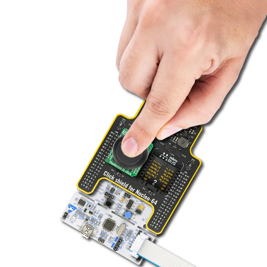
Button G Click
Dev. board
Arduino UNO Rev3
Compiler
NECTO Studio
MCU
ATmega328P
Enhance user engagement and interaction by incorporating the green-ringed button, which lights up when pressed, making actions more dynamic and visually captivating
A
A
Hardware Overview
How does it work?
Button G Click is based on the 3006.2117, a tactile switch with an integrated independent green LED from Marquardt. The tactile switch has a debounce circuit to eliminate the ripple signal and provide a clean transition at its output and is pulled down. The round transparent button of the tactile switch is 6.8mm in diameter and has a green LED background light. This LED can be programmed as feedback to the user to make a visual expression of knowing the contact has been
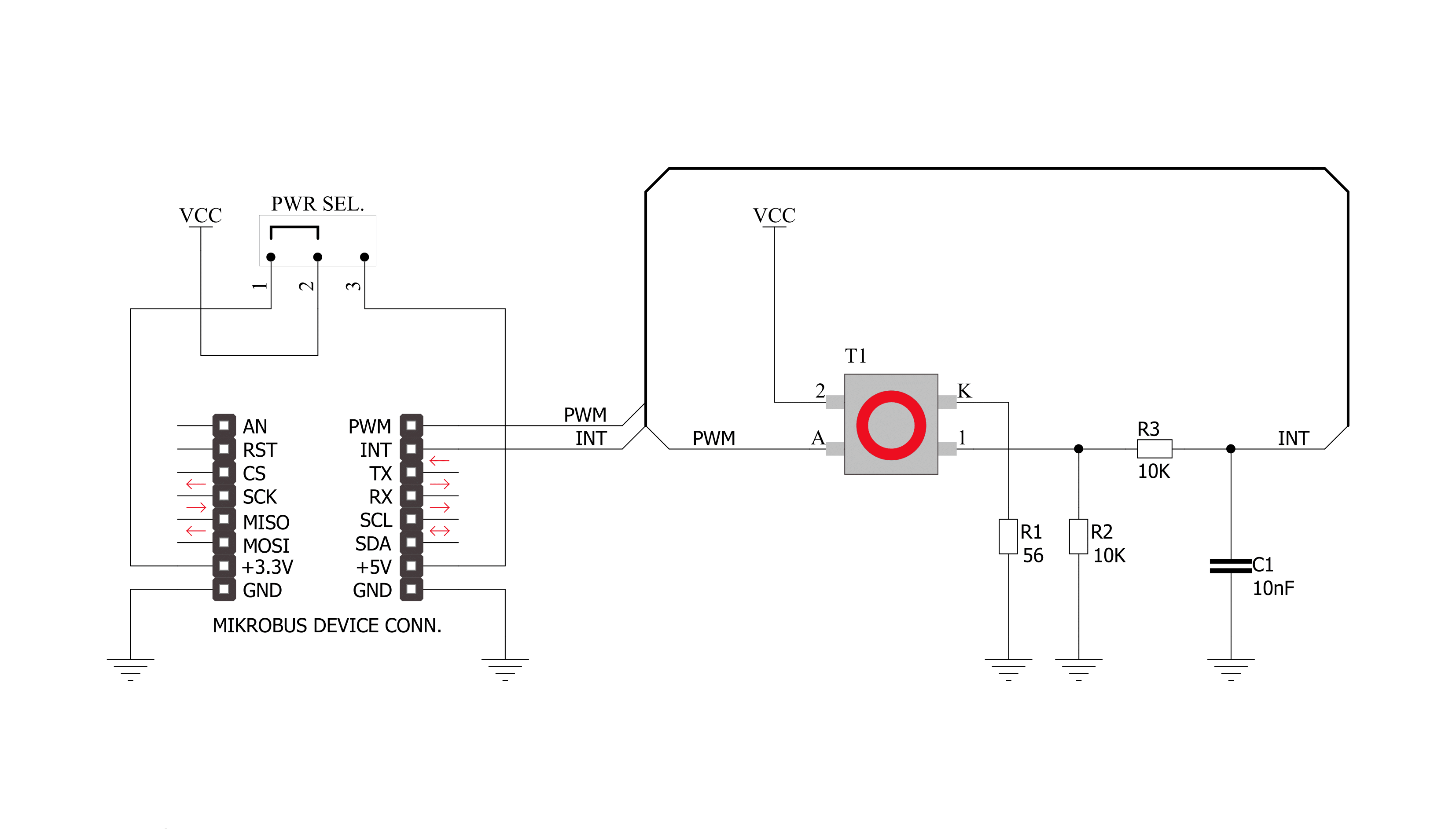
made. Since the backlight LED is controlled independently, it can be programmed in different patterns, such as varying light levels, light intensity, or blinking rate on subsequent button presses, thus giving additional feedback to the end user. The tactile button of this Click board™ sends an interrupt signal to the host MCU using the INT pin of the mikroBUS™ socket. The host MCU can control the integrated red LED using the PWM pin of the mikroBUS™ socket. The Pulse
Width Modulation (PWM) lets you program this LED using various blinking patterns and light intensity. This Click board™ can operate with either 3.3V or 5V logic voltage levels selected via the PWR SEL jumper. This way, both 3.3V and 5V capable MCUs can use the communication lines properly. Also, this Click board™ comes equipped with a library containing easy-to-use functions and an example code that can be used as a reference for further development.

Features overview
Development board
Arduino UNO is a versatile microcontroller board built around the ATmega328P chip. It offers extensive connectivity options for various projects, featuring 14 digital input/output pins, six of which are PWM-capable, along with six analog inputs. Its core components include a 16MHz ceramic resonator, a USB connection, a power jack, an
ICSP header, and a reset button, providing everything necessary to power and program the board. The Uno is ready to go, whether connected to a computer via USB or powered by an AC-to-DC adapter or battery. As the first USB Arduino board, it serves as the benchmark for the Arduino platform, with "Uno" symbolizing its status as the
first in a series. This name choice, meaning "one" in Italian, commemorates the launch of Arduino Software (IDE) 1.0. Initially introduced alongside version 1.0 of the Arduino Software (IDE), the Uno has since become the foundational model for subsequent Arduino releases, embodying the platform's evolution.

Microcontroller Overview
MCU Card / MCU

Architecture
AVR
MCU Memory (KB)
32
Silicon Vendor
Microchip
Pin count
28
RAM (Bytes)
2048
You complete me!
Accessories
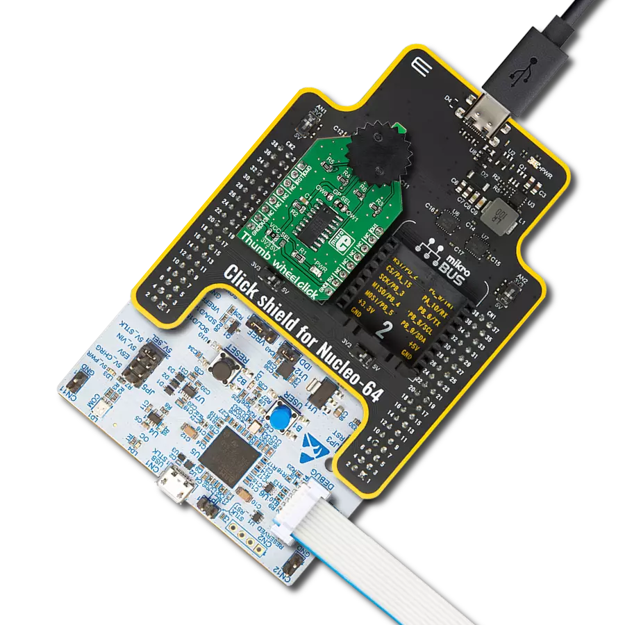
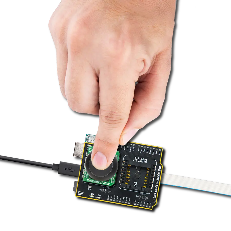
Click Shield for Arduino UNO has two proprietary mikroBUS™ sockets, allowing all the Click board™ devices to be interfaced with the Arduino UNO board without effort. The Arduino Uno, a microcontroller board based on the ATmega328P, provides an affordable and flexible way for users to try out new concepts and build prototypes with the ATmega328P microcontroller from various combinations of performance, power consumption, and features. The Arduino Uno has 14 digital input/output pins (of which six can be used as PWM outputs), six analog inputs, a 16 MHz ceramic resonator (CSTCE16M0V53-R0), a USB connection, a power jack, an ICSP header, and reset button. Most of the ATmega328P microcontroller pins are brought to the IO pins on the left and right edge of the board, which are then connected to two existing mikroBUS™ sockets. This Click Shield also has several switches that perform functions such as selecting the logic levels of analog signals on mikroBUS™ sockets and selecting logic voltage levels of the mikroBUS™ sockets themselves. Besides, the user is offered the possibility of using any Click board™ with the help of existing bidirectional level-shifting voltage translators, regardless of whether the Click board™ operates at a 3.3V or 5V logic voltage level. Once you connect the Arduino UNO board with our Click Shield for Arduino UNO, you can access hundreds of Click boards™, working with 3.3V or 5V logic voltage levels.

Used MCU Pins
mikroBUS™ mapper
Take a closer look
Click board™ Schematic
Step by step
Project assembly

Start by selecting your development board and Click board™. Begin with the Arduino UNO Rev3 as your development board.


Software Support
Library Description
This library contains API for Button G Click driver.
Key functions:
buttong_pwm_stop- This function stops the PWM moudle outputbuttong_pwm_start- This function starts the PWM moudle outputbuttong_get_button_state- This function reads the digital signal from the INT pin which tells us whether the button has been pressed or not
Open Source
Code example
The complete application code and a ready-to-use project are available through the NECTO Studio Package Manager for direct installation in the NECTO Studio. The application code can also be found on the MIKROE GitHub account.
/*!
 * @file main.c
 * @brief Button G Click example
 *
 * # Description
 * This library contains API for Button G Click driver.
 * One library is used for every single one of them.
 * They are simple touch detectors that send a pressed/released
 * signal and receive a PWM output which controls the backlight on the button.
 *
 * The demo application is composed of two sections :
 *
 * ## Application Init
 * This function initializes and configures the logger and Click modules.
 *
 * ## Application Task
 * This example first increases the backlight on the button and then decreases the intensity of the backlight. When the button is pressed,
 * reports the event in the console using UART communication.
 *
 * @author Nikola Peric
 *
 */

#include "board.h"
#include "log.h"
#include "buttong.h"

static buttong_t buttong;
static log_t logger;

void application_init ( void )
{
    log_cfg_t log_cfg;          /**< Logger config object. */
    buttong_cfg_t buttong_cfg;  /**< Click config object. */

    /**
     * Logger initialization.
     * Default baud rate: 115200
     * Default log level: LOG_LEVEL_DEBUG
     * @note If USB_UART_RX and USB_UART_TX
     * are defined as HAL_PIN_NC, you will
     * need to define them manually for log to work.
     * See @b LOG_MAP_USB_UART macro definition for detailed explanation.
     */
    LOG_MAP_USB_UART( log_cfg );
    log_init( &logger, &log_cfg );
    log_info( &logger, " Application Init " );

    // Click initialization.

    buttong_cfg_setup( &buttong_cfg );
    BUTTONG_MAP_MIKROBUS( buttong_cfg, MIKROBUS_1 );
    err_t init_flag  = buttong_init( &buttong, &buttong_cfg );
    if ( PWM_ERROR == init_flag )
    {
        log_error( &logger, " Application Init Error. " );
        log_info( &logger, " Please, run program again... " );

        for ( ; ; );
    }
    Delay_ms ( 500 );

    buttong_set_duty_cycle ( &buttong, 0.0 );
    buttong_pwm_start( &buttong );

    log_info( &logger, " Application Task " );
}

void application_task ( void )
{
    static float duty_cycle;
    static uint8_t button_state;
    static uint8_t button_state_old;

    button_state = buttong_get_button_state( &buttong );

    if ( button_state && ( button_state != button_state_old ) )
    {
        log_printf( &logger, " <-- Button pressed --> \r\n" );
        for ( uint8_t n_cnt = 1; n_cnt <= 100; n_cnt++  )
        {
            duty_cycle = ( float ) n_cnt ;
            duty_cycle /= 100;
            buttong_set_duty_cycle( &buttong, duty_cycle );
            Delay_ms ( 10 );
        }
        button_state_old = button_state;
    }
    else if ( !button_state && ( button_state != button_state_old ) )
    {
        for ( uint8_t n_cnt = 100; n_cnt > 0; n_cnt-- )
        {
            duty_cycle = ( float ) n_cnt ;
            duty_cycle /= 100;
            buttong_set_duty_cycle( &buttong,  duty_cycle );
            Delay_ms ( 10 );
        }
        button_state_old = button_state;
    }
}

int main ( void )
{
    /* Do not remove this line or clock might not be set correctly. */
    #ifdef PREINIT_SUPPORTED
    preinit();
    #endif

    application_init( );

    for ( ; ; )
    {
        application_task( );
    }

    return 0;
}

// ------------------------------------------------------------------------ END
Additional Support
Resources
Category:Pushbutton/Switches