Embark on a green charge journey with EM8500 and STM32L073RZ
Empower your batteries with the energy of the sun!

Published Feb 26, 2024
Click board™
Solar Energy 2 Click
Dev. board
Nucleo-64 with STM32L073RZ MCU
Compiler
NECTO Studio
MCU
STM32L073RZ
From ray to recharge, our solution merges the brilliance of solar energy with battery efficiency. Experience our newest eco-friendly power solution and secure a sustainable future for your devices.
A
A
Hardware Overview
How does it work?
Solar Energy 2 Click is based on the EM8500, a power management controller with an energy harvesting interface from EM Microelectronic. The EM8500 is flexible in operation and can use different energy banks such as primary cell batteries, gold capacitors, and supercapacitors. It can work in harvesting sources in μW to mW range thanks to an ultra-low power DC-DC boost converter with very high efficiency. The EN8500 uses short-term storage (STS) element (100μF capacitor) to speed up system start-up. Besides fast start-up time over battery power, the LTS element (long-term storage) controls the minimum and maximum voltages, thus preventing damage to the battery. The onboard PMU with a built-in mechanism will extend the battery life if using a non-rechargeable battery. The Solar Energy 2 Click can supply the external application through the VSUP and VAUX0-2 pins and correspondent GNDs of the 12-pin AUX COM header. On the VSUP pin, which is the main supply output, the wake-up function allows the automatic enabling of the supply after a given time. The AUX (auxiliary) output pins can output regulated voltages from 1.2 to 2.6V. Onboard EEPROM stores device configuration data, such as minimum and maximum voltage monitors, which will stop the DC-DC convertor, thus limiting the
power loss. On EEPROM, data for the VAUX0-2 and VGND0-2 pins, besides the voltage output, can be stored to store data for disconnecting any of these pins. There are three modes in which Solar Energy 2 Click can operate. In Normal mode, the battery is connected and is in operating range. The LTS Protection mode is activated when the LTS voltage drops below minimum battery operation. In this mode, it is activated under-voltage protection. Finally, there is a Sleep mode where the VSUP is not supplied, and the communication with the host MCU is off. Sleep mode exit can be activated over the wake-up pin or by an internal timer. The EN8500 also has features such as under-voltage, over-voltage, min/max voltage warning, USB connected status, lux-meter, and more. The lux-meter can run in three modes: Fully Automatic mode, Automatic Range Selection, and Fully Manual mode. The lux-meter determines current ranges by the harvesting element in 1 μA steps. On Solar Energy 2 Click, a VIN SEL switch allows the EN8500 to use the 5V rail from the mikroBUS™ socket or the 5V from the onboard USB Type-C connector as its supply. The EM8500 can detect the power on this line but can't determine if it is from the USB C or the 5V rail of the mikroBUS™ socket. Although the EN8500 uses 5V rail only for its power management, the Solar Energy 2 Click
can work with 3.3V systems, too. This Click board™ features the PCA9306, a dual bidirectional voltage level translator from Texas Instruments. As a low-voltage-side reference voltage, this translator uses the VSUP from the EN8500, while the high-side is selected via the VCC SEL jumper. In the same manner, several MOSFETs are used for other onboard interconnections. Solar Energy 2 Click uses a standard 2-Wire I2C interface to communicate with the host MCU and supports Standard, Fast, and High-Speed communication. As mentioned, the EN8500 can exit sleep mode via the wake-up functions, which can be the WUP pin of the mikroBUS™ socket or the WUP pin of the AUX COM header. The EN8500 uses two more pins to send statuses to the host MCU. The HLV is used as a harvester-energy levels detection status, while the BLV is used for battery voltage levels monitoring. This Click board™ can operate with either 3.3V or 5V logic voltage levels selected via the VCC SEL jumper. This way, both 3.3V and 5V capable MCUs can use the communication lines properly. Also, this Click board™ comes equipped with a library containing easy-to-use functions and an example code that can be used as a reference for further development.

Features overview
Development board
Nucleo-64 with STM32L073RZ MCU offers a cost-effective and adaptable platform for developers to explore new ideas and prototype their designs. This board harnesses the versatility of the STM32 microcontroller, enabling users to select the optimal balance of performance and power consumption for their projects. It accommodates the STM32 microcontroller in the LQFP64 package and includes essential components such as a user LED, which doubles as an ARDUINO® signal, alongside user and reset push-buttons, and a 32.768kHz crystal oscillator for precise timing operations. Designed with expansion and flexibility in mind, the Nucleo-64 board features an ARDUINO® Uno V3 expansion connector and ST morpho extension pin
headers, granting complete access to the STM32's I/Os for comprehensive project integration. Power supply options are adaptable, supporting ST-LINK USB VBUS or external power sources, ensuring adaptability in various development environments. The board also has an on-board ST-LINK debugger/programmer with USB re-enumeration capability, simplifying the programming and debugging process. Moreover, the board is designed to simplify advanced development with its external SMPS for efficient Vcore logic supply, support for USB Device full speed or USB SNK/UFP full speed, and built-in cryptographic features, enhancing both the power efficiency and security of projects. Additional connectivity is
provided through dedicated connectors for external SMPS experimentation, a USB connector for the ST-LINK, and a MIPI® debug connector, expanding the possibilities for hardware interfacing and experimentation. Developers will find extensive support through comprehensive free software libraries and examples, courtesy of the STM32Cube MCU Package. This, combined with compatibility with a wide array of Integrated Development Environments (IDEs), including IAR Embedded Workbench®, MDK-ARM, and STM32CubeIDE, ensures a smooth and efficient development experience, allowing users to fully leverage the capabilities of the Nucleo-64 board in their projects.

Microcontroller Overview
MCU Card / MCU

Architecture
ARM Cortex-M0
MCU Memory (KB)
192
Silicon Vendor
STMicroelectronics
Pin count
64
RAM (Bytes)
20480
You complete me!
Accessories
Click Shield for Nucleo-64 comes equipped with two proprietary mikroBUS™ sockets, allowing all the Click board™ devices to be interfaced with the STM32 Nucleo-64 board with no effort. This way, Mikroe allows its users to add any functionality from our ever-growing range of Click boards™, such as WiFi, GSM, GPS, Bluetooth, ZigBee, environmental sensors, LEDs, speech recognition, motor control, movement sensors, and many more. More than 1537 Click boards™, which can be stacked and integrated, are at your disposal. The STM32 Nucleo-64 boards are based on the microcontrollers in 64-pin packages, a 32-bit MCU with an ARM Cortex M4 processor operating at 84MHz, 512Kb Flash, and 96KB SRAM, divided into two regions where the top section represents the ST-Link/V2 debugger and programmer while the bottom section of the board is an actual development board. These boards are controlled and powered conveniently through a USB connection to program and efficiently debug the Nucleo-64 board out of the box, with an additional USB cable connected to the USB mini port on the board. Most of the STM32 microcontroller pins are brought to the IO pins on the left and right edge of the board, which are then connected to two existing mikroBUS™ sockets. This Click Shield also has several switches that perform functions such as selecting the logic levels of analog signals on mikroBUS™ sockets and selecting logic voltage levels of the mikroBUS™ sockets themselves. Besides, the user is offered the possibility of using any Click board™ with the help of existing bidirectional level-shifting voltage translators, regardless of whether the Click board™ operates at a 3.3V or 5V logic voltage level. Once you connect the STM32 Nucleo-64 board with our Click Shield for Nucleo-64, you can access hundreds of Click boards™, working with 3.3V or 5V logic voltage levels.

Solar Panel offers an efficient alternative powering solution for your device, harnessing the remarkable photoelectric effect to generate electricity when exposed to sunlight. Comprising monocrystalline silicon solar cells encapsulated with PC film lamination, this panel ensures durability and protection from environmental elements. The magic lies in the photoelectric effect, where sunlight excites electrons in the silicon cells, creating an electric current. The panel's construction optimizes sunlight absorption and conversion, enabling it to generate a minimum output of 4.0V. It can produce electrical power under a maximum load of 100mA, making it ideal for various applications. This solar panel offers a sustainable and eco-friendly approach, providing a renewable energy source that reduces reliance on conventional power grids and promotes environmental consciousness.

Li-Polymer Battery is the ideal solution for devices that demand a dependable and long-lasting power supply while emphasizing mobility. Its compatibility with mikromedia boards ensures easy integration without additional modifications. With a voltage output of 3.7V, the battery meets the standard requirements of many electronic devices. Additionally, boasting a capacity of 2000mAh, it can store a substantial amount of energy, providing sustained power for extended periods. This feature minimizes the need for frequent recharging or replacement. Overall, the Li-Polymer Battery is a reliable and autonomous power source, ideally suited for devices requiring a stable and enduring energy solution. You can find a more extensive choice of Li-Polymer batteries in our offer.

Used MCU Pins
mikroBUS™ mapper
Take a closer look
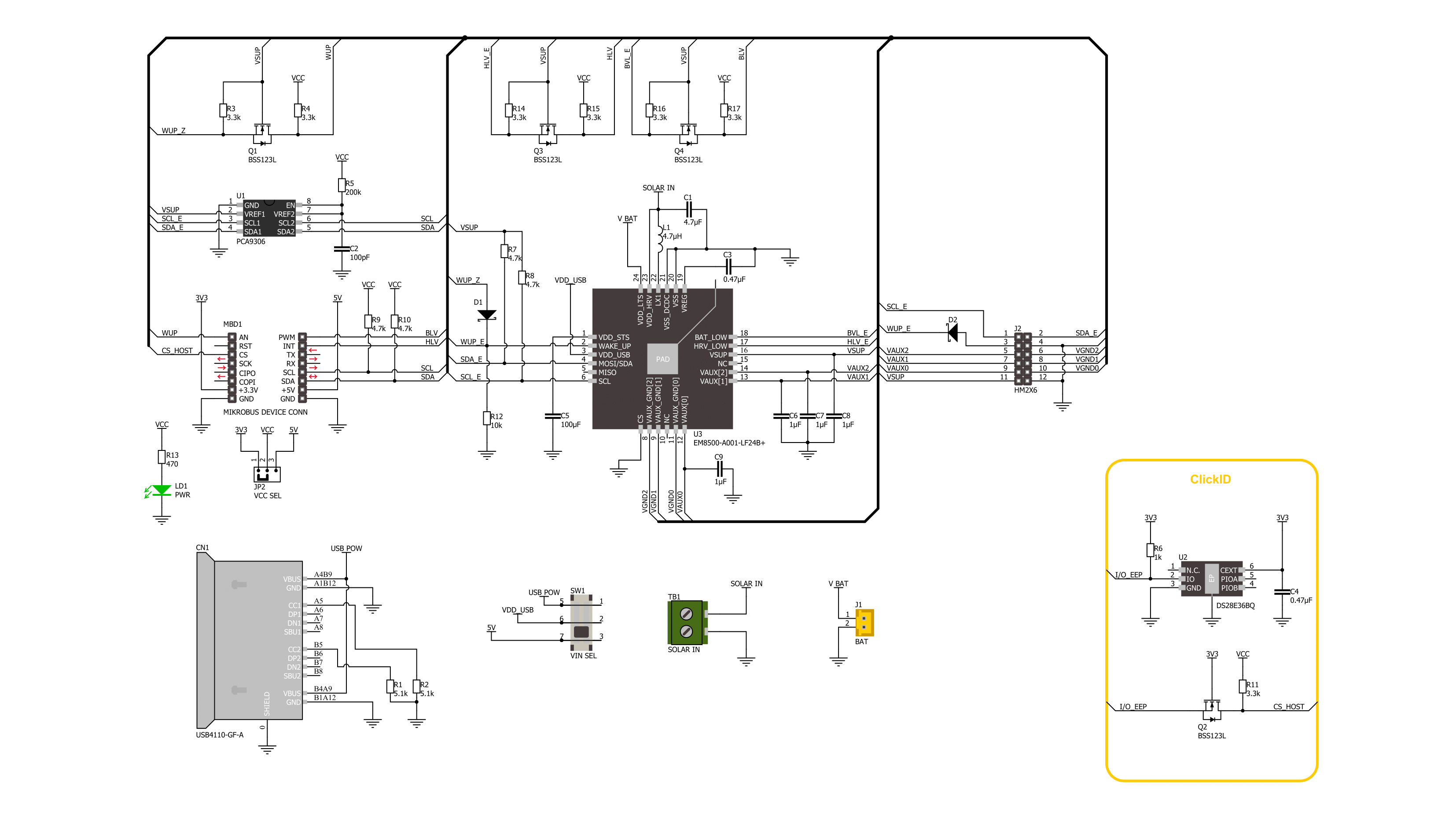
Click board™ Schematic
Step by step
Project assembly
Start by selecting your development board and Click board™. Begin with the Nucleo-64 with STM32L073RZ MCU as your development board.


Track your results in real time
Application Output
1. Application Output - In Debug mode, the 'Application Output' window enables real-time data monitoring, offering direct insight into execution results. Ensure proper data display by configuring the environment correctly using the provided tutorial.

2. UART Terminal - Use the UART Terminal to monitor data transmission via a USB to UART converter, allowing direct communication between the Click board™ and your development system. Configure the baud rate and other serial settings according to your project's requirements to ensure proper functionality. For step-by-step setup instructions, refer to the provided tutorial.

3. Plot Output - The Plot feature offers a powerful way to visualize real-time sensor data, enabling trend analysis, debugging, and comparison of multiple data points. To set it up correctly, follow the provided tutorial, which includes a step-by-step example of using the Plot feature to display Click board™ readings. To use the Plot feature in your code, use the function: plot(*insert_graph_name*, variable_name);. This is a general format, and it is up to the user to replace 'insert_graph_name' with the actual graph name and 'variable_name' with the parameter to be displayed.

Software Support
Library Description
This library contains API for Solar Energy 2 Click driver.
Key functions:
solarenergy2_set_pwr_current_source- Solar Energy 2 power source selection function.solarenergy2_config_abs_voltage- Solar Energy 2 config absolute voltage function.solarenergy2_set_mppt_ratio- Solar Energy 2 set MPPT ratio function.
Open Source
Code example
The complete application code and a ready-to-use project are available through the NECTO Studio Package Manager for direct installation in the NECTO Studio. The application code can also be found on the MIKROE GitHub account.
/*!
 * @file main.c
 * @brief Solar Energy 2 Click example
 *
 * # Description
 * This library contains API for the Solar Energy 2 Click driver.
 * This driver provides functions to configure the
 * power management controller with an energy harvesting interface.
 *
 * The demo application is composed of two sections :
 *
 * ## Application Init
 * Initialization of I2C module and log UART.
 * After driver initialization, the app set default settings.
 *
 * ## Application Task
 * This is an example that shows the use of Solar Energy 2 Click board™.
 * The following example will charge the battery
 * if it is below the maximum voltage of the application of 3.40 V,
 * stop charging when the battery is full and monitor additional status and
 * storage element voltage information.
 * Results are being sent to the Usart Terminal where you can track their changes.
 *
 * @author Nenad Filipovic
 *
 */

#include "board.h"
#include "log.h"
#include "solarenergy2.h"

static solarenergy2_t solarenergy2;
static log_t logger;
static solarenergy2_status_t status;
static solarenergy2_bat_vtg_status_t vld_status;

void display_status ( void )
{
    log_printf( &logger, "----------------------------\r\n" );
    if ( status.hrv_low )
    {
        log_printf( &logger, " HRV energy level too low for harvesting.\r\n" );
    }
    else
    {
        log_printf( &logger, " HRV has enough energy to be harvested.\r\n" );
    }

    if ( status.bat_low )
    {
        log_printf( &logger, " LTS voltage lower than min battery maintenance voltage.\r\n" );
    }
    else
    {
        log_printf( &logger, " LTS voltage higher than min battery maintenance voltage.\r\n" );
    }

    if ( status.sw_vdcdc_lts_nsts )
    {
        if ( vld_status.sts_apl_max_lo || vld_status.sts_apl_max_hi )
        {
            log_printf( &logger, " The battery is not charging.\r\n" );
        }
        else
        {
            log_printf( &logger, " The battery is charging.\r\n" );
        }
    }

    if ( status.sw_vdcdc_lts_nsts )
    {
        log_printf( &logger, " The power supply has been detected.\r\n" );
    }
    else
    {
        log_printf( &logger, " No power supply.\r\n" );
    }
}

void application_init ( void )
{
    log_cfg_t log_cfg;  /**< Logger config object. */
    solarenergy2_cfg_t solarenergy2_cfg;  /**< Click config object. */

    /**
     * Logger initialization.
     * Default baud rate: 115200
     * Default log level: LOG_LEVEL_DEBUG
     * @note If USB_UART_RX and USB_UART_TX
     * are defined as HAL_PIN_NC, you will
     * need to define them manually for log to work.
     * See @b LOG_MAP_USB_UART macro definition for detailed explanation.
     */
    LOG_MAP_USB_UART( log_cfg );
    log_init( &logger, &log_cfg );
    log_info( &logger, " Application Init " );

    // Click initialization.
    solarenergy2_cfg_setup( &solarenergy2_cfg );
    SOLARENERGY2_MAP_MIKROBUS( solarenergy2_cfg, MIKROBUS_1 );
    if ( I2C_MASTER_ERROR == solarenergy2_init( &solarenergy2, &solarenergy2_cfg ) )
    {
        log_error( &logger, " Communication init." );
        for ( ; ; );
    }

    if ( SOLARENERGY2_ERROR == solarenergy2_default_cfg ( &solarenergy2 ) )
    {
        log_error( &logger, " Default configuration." );
        for ( ; ; );
    }

    log_info( &logger, " Application Task " );
    Delay_ms( 100 );
}

void application_task ( void )
{
    if ( SOLARENERGY2_OK == solarenergy2_get_status( &solarenergy2, &status ) )
    {
        if  ( SOLARENERGY2_OK == solarenergy2_get_bat_vtg_status( &solarenergy2, &vld_status ) )
        {
            display_status( );
        }
    }
    Delay_ms( 5000 );
}

void main ( void )
{
    application_init( );

    for ( ; ; )
    {
        application_task( );
    }
}

// ------------------------------------------------------------------------ END
Additional Support
Resources
Category:Battery charger


