Experience a new level of precision in differential pressure measurement with MPXV5010DP and ATmega328P
Measure the delta: Your ultimate differential pressure sensor partner!

Published Feb 14, 2024
Click board™
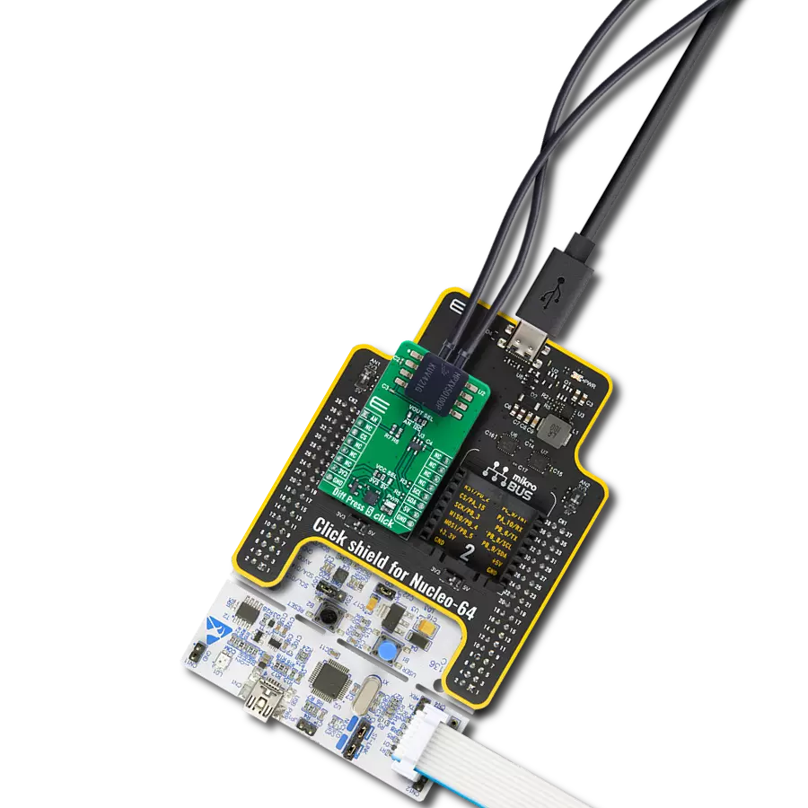
Diff pressure Click
Dev. board
Arduino UNO Rev3
Compiler
NECTO Studio
MCU
ATmega328P
Our advanced differential pressure sensor empowers you to capture nuanced variations in pressure, providing critical insights for applications in HVAC, industrial processes, and beyond
A
A
Hardware Overview
How does it work?
Diff Pressure Click is based on the MPXV5010DP, an integrated silicon pressure sensor on-chip signal conditioned, temperature compensated, and calibrated from NXP Semiconductor. This piezoresistive transducer combines advanced micromachining techniques, thin-film metallization, and bipolar processing to provide an accurate, high-level output signal proportional to the applied pressure. The two ports are designated as a Pressure side (P1) and a Vacuum side (P2), and the sensor is designed to operate with a positive differential pressure where P1 > P2. It can handle
pressure from 0 up to 10KPa, with a maximum error rate of 5.0% in the temperature range between 0°and 85°C. The MPXV5010DP has an analog output; thus, this Click board™ features the MCP3551, a low-power, single-channel 22-bit Delta-Sigma ADC from Microchip. The analog signal passes through this ADC to the host MCU with high accuracy, low noise, and a high oversampling rate. The Diff Pressure uses the MCP3551 and its 3-wire SPI serial interface to communicate with the host MCU over the mikroBUS™ socket, supporting SPI 0 and 1 modes with maximum speeds of up to
5MHz. For voltage logic level translation, this Click board™ features the TXB0106, a 6-bit bidirectional level-shifting and voltage translator with auto-direction sensing and ESD protection from Texas Instruments. This Click board™ can operate with either 3.3V or 5V logic voltage levels selected via the 3V3 5V jumper. This way, both 3.3V and 5V capable MCUs can use the communication lines properly. Also, this Click board™ comes equipped with a library containing easy-to-use functions and an example code that can be used as a reference for further development.

Features overview
Development board
Arduino UNO is a versatile microcontroller board built around the ATmega328P chip. It offers extensive connectivity options for various projects, featuring 14 digital input/output pins, six of which are PWM-capable, along with six analog inputs. Its core components include a 16MHz ceramic resonator, a USB connection, a power jack, an
ICSP header, and a reset button, providing everything necessary to power and program the board. The Uno is ready to go, whether connected to a computer via USB or powered by an AC-to-DC adapter or battery. As the first USB Arduino board, it serves as the benchmark for the Arduino platform, with "Uno" symbolizing its status as the
first in a series. This name choice, meaning "one" in Italian, commemorates the launch of Arduino Software (IDE) 1.0. Initially introduced alongside version 1.0 of the Arduino Software (IDE), the Uno has since become the foundational model for subsequent Arduino releases, embodying the platform's evolution.

Microcontroller Overview
MCU Card / MCU

Architecture
AVR
MCU Memory (KB)
32
Silicon Vendor
Microchip
Pin count
28
RAM (Bytes)
2048
You complete me!
Accessories
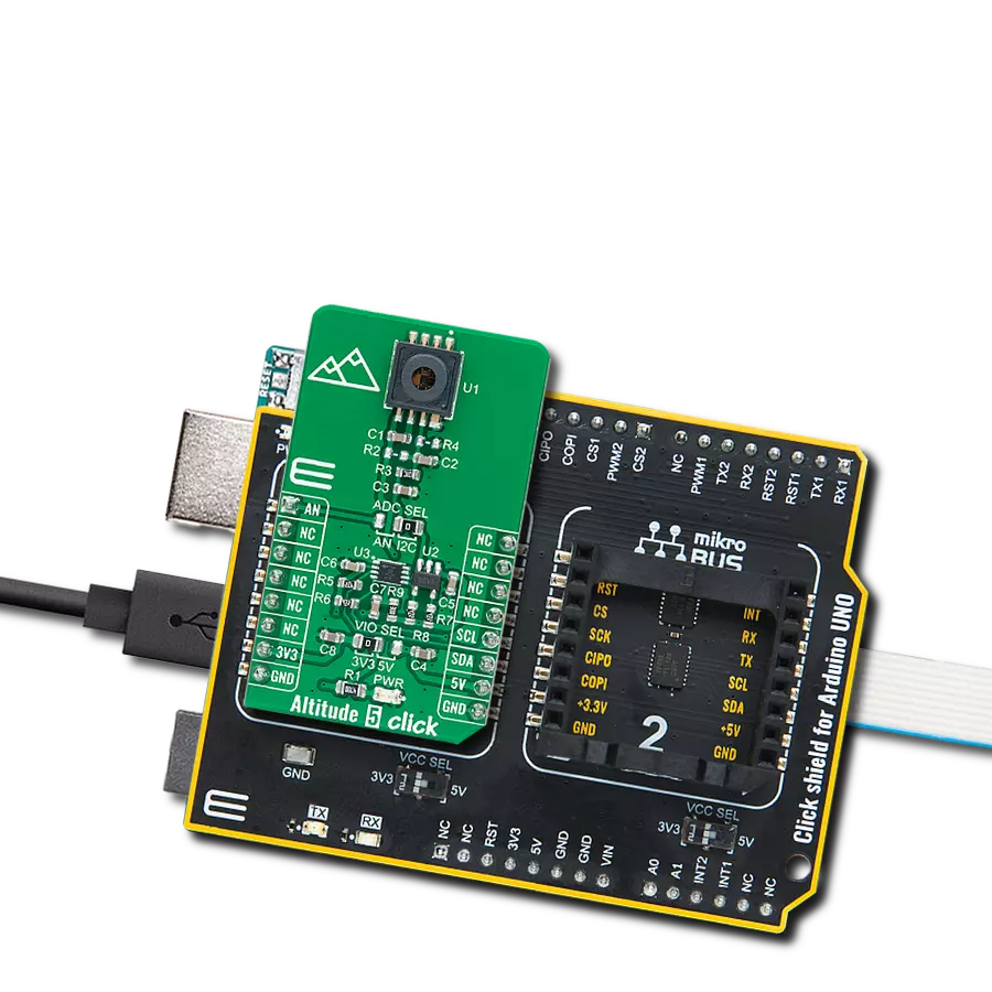
Click Shield for Arduino UNO has two proprietary mikroBUS™ sockets, allowing all the Click board™ devices to be interfaced with the Arduino UNO board without effort. The Arduino Uno, a microcontroller board based on the ATmega328P, provides an affordable and flexible way for users to try out new concepts and build prototypes with the ATmega328P microcontroller from various combinations of performance, power consumption, and features. The Arduino Uno has 14 digital input/output pins (of which six can be used as PWM outputs), six analog inputs, a 16 MHz ceramic resonator (CSTCE16M0V53-R0), a USB connection, a power jack, an ICSP header, and reset button. Most of the ATmega328P microcontroller pins are brought to the IO pins on the left and right edge of the board, which are then connected to two existing mikroBUS™ sockets. This Click Shield also has several switches that perform functions such as selecting the logic levels of analog signals on mikroBUS™ sockets and selecting logic voltage levels of the mikroBUS™ sockets themselves. Besides, the user is offered the possibility of using any Click board™ with the help of existing bidirectional level-shifting voltage translators, regardless of whether the Click board™ operates at a 3.3V or 5V logic voltage level. Once you connect the Arduino UNO board with our Click Shield for Arduino UNO, you can access hundreds of Click boards™, working with 3.3V or 5V logic voltage levels.

Used MCU Pins
mikroBUS™ mapper
Take a closer look
Click board™ Schematic

Step by step
Project assembly

Start by selecting your development board and Click board™. Begin with the Arduino UNO Rev3 as your development board.


Software Support
Library Description
This library contains API for Diff pressure Click driver.
Key functions:
diffpressure_read_adc_voltage- This function read ADC voltage value from Diff Pressure clickdiffpressure_get_pa_difference- This function get pressure difference [Pa]
Open Source
Code example
The complete application code and a ready-to-use project are available through the NECTO Studio Package Manager for direct installation in the NECTO Studio. The application code can also be found on the MIKROE GitHub account.
/*!
 * \file
 * \brief Diff pressure Click example
 *
 * # Description
 * This application is temperature compensated and calibrated pressure sensor.
 *
 * The demo application is composed of two sections :
 *
 * ## Application Init
 * Initializes the driver and logger.
 *
 * ## Application Task
 * This is an example which demonstrates the use of Diff Pressure Click board.
 * The example reads the values of ADC module (MPC3551) 22-bit register value
 * converted to voltage and the pressure difference [ Pa ] and displays
 * those values on the USB UART.
 *
 * \author MikroE Team
 *
 */
// ------------------------------------------------------------------- INCLUDES

#include "board.h"
#include "log.h"
#include "diffpressure.h"

// ------------------------------------------------------------------ VARIABLES

static diffpressure_t diffpressure;
static log_t logger;

// ------------------------------------------------------ APPLICATION FUNCTIONS

void application_init ( void )
{
    log_cfg_t log_cfg;
    diffpressure_cfg_t cfg;

    /**
     * Logger initialization.
     * Default baud rate: 115200
     * Default log level: LOG_LEVEL_DEBUG
     * @note If USB_UART_RX and USB_UART_TX
     * are defined as HAL_PIN_NC, you will
     * need to define them manually for log to work.
     * See @b LOG_MAP_USB_UART macro definition for detailed explanation.
     */
    LOG_MAP_USB_UART( log_cfg );
    log_init( &logger, &log_cfg );
    log_info( &logger, " Application Init " );

    // Click initialization.
    diffpressure_cfg_setup( &cfg );
    DIFFPRESSURE_MAP_MIKROBUS( cfg, MIKROBUS_1 );
    if ( DIFFPRESSURE_OK != diffpressure_init( &diffpressure, &cfg ) )
    {
        log_error( &logger, " Communication init." );
        for ( ; ; );
    }

    log_info( &logger, " Application Task " );
}

void application_task ( void )
{
    float adc_voltage = 0;
    int32_t difference = 0;

    adc_voltage = diffpressure_read_adc_voltage( &diffpressure );
    difference = diffpressure_get_pa_difference( &diffpressure, adc_voltage );

    log_printf( &logger, " ADC Voltage: %.3f [V]\r\n", adc_voltage );

    log_printf( &logger, " Pressure Diff: %ld [Pa]\r\n\n", difference );

    Delay_ms ( 100 );
}

int main ( void )
{
    /* Do not remove this line or clock might not be set correctly. */
    #ifdef PREINIT_SUPPORTED
    preinit();
    #endif

    application_init( );

    for ( ; ; )
    {
        application_task( );
    }

    return 0;
}


// ------------------------------------------------------------------------ END
Additional Support
Resources
Category:Pressure