Experience the transformation of location-based experiences with NEO-M8J and ATmega328P
Unlocking precision, unleashing adventure
Published Feb 14, 2024
Click board™
GNSS 10 Click
Dev. board
Arduino UNO Rev3
Compiler
NECTO Studio
MCU
ATmega328P
With accuracy that goes beyond maps, you'll unlock new dimensions of navigation, enabling you to navigate even the most intricate routes effortlessly.
A
A
Hardware Overview
How does it work?
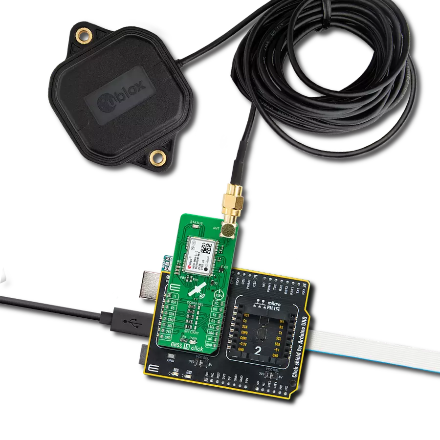
GNSS 10 Click is based on the NEO-M8J, a high-performance GNSS module from u-blox. This module is built on the high-performing M8 GNSS engine in the industry-proven NEO form factor. It utilizes concurrent reception of up to three GNSS systems (GPS/Galileo with BeiDou or GLONASS), recognizes multiple constellations, and provides outstanding positioning accuracy in scenarios involving urban canyons or weak signals. The NEO-M8J offers high sensitivity and minimal acquisition times while maintaining low system power. For even better and faster positioning improvement, the NEO-M8J supports the augmentation of QZSS, GAGAN, and IMES together with WAAS, EGNOS, and MSAS. The future-proof NEO-M8J includes an internal Flash that allows future firmware updates, ideally suited to industrial and automotive applications. It also supports message integrity protection, geofencing, and spoofing detection with configurable interface settings to fit customer applications easily. This Click board™ comes with a configurable host interface, allowing you to choose communication with MCU using the UART, SPI, or I2C interface. The interface can be selected by
positioning SMD jumpers labeled COMM SEL in an appropriate position. Note that all the jumpers' positions must be on the same side, or the Click board™ may become unresponsive. In this case, the SPI represents its default communication protocol. When selecting the SPI communication, it is mandatory to leave the jumper to DSEL populated, the first jumper at the top of the COMM SEL jumpers, to configure the interface pins as SPI. SPI interface can't be used simultaneously with UART/I2C. To activate the UART/I2C selection, the jumper labeled as DSEL must be unpopulated. It is also equipped with a USB type C connector for a USB version 2.0 FS (Full Speed, 12 Mbit/s) compatible interface, available for communication as an alternative to the UART. With the help of the active USB voltage, the necessary power supply of the USB power block of the NEO-M8J is provided via the ADP1715 linear regulator. In the case of the primary supply failure, the module can use a backup supply voltage from a connected battery if you need the Click board™ to be a standalone device. Backup voltage supplies the real-time clock and battery-backed RAM and enables all relevant data to be saved in
the backup RAM to allow a hot or warm start later. In addition to these features, it also uses several GPIO pins. An active-low reset signal routed on the RST pin of the mikroBUS™ socket activates a hardware reset of the system, while the INT pin on the mikroBUS™ socket represents a standard interrupt feature providing a user with feedback information. It also has an additional interrupt marked as I1 and routed on the AN pin of the mikroBUS™ socket, used for the module Wake-Up function, alongside a blue LED indicator marked as STATUS used for time pulse signal indication. GNSS 10 Click possesses the SMA antenna connector with an impedance of 50Ω, which can connect the appropriate active antenna that MIKROE offers for improved range and received signal strength. This Click board™ can be operated only with a 3.3V logic voltage level. The board must perform appropriate logic voltage level conversion before using MCUs with different logic levels. Also, it comes equipped with a library containing functions and an example code that can be used as a reference for further development.

Features overview
Development board
Arduino UNO is a versatile microcontroller board built around the ATmega328P chip. It offers extensive connectivity options for various projects, featuring 14 digital input/output pins, six of which are PWM-capable, along with six analog inputs. Its core components include a 16MHz ceramic resonator, a USB connection, a power jack, an
ICSP header, and a reset button, providing everything necessary to power and program the board. The Uno is ready to go, whether connected to a computer via USB or powered by an AC-to-DC adapter or battery. As the first USB Arduino board, it serves as the benchmark for the Arduino platform, with "Uno" symbolizing its status as the
first in a series. This name choice, meaning "one" in Italian, commemorates the launch of Arduino Software (IDE) 1.0. Initially introduced alongside version 1.0 of the Arduino Software (IDE), the Uno has since become the foundational model for subsequent Arduino releases, embodying the platform's evolution.

Microcontroller Overview
MCU Card / MCU

Architecture
AVR
MCU Memory (KB)
32
Silicon Vendor
Microchip
Pin count
28
RAM (Bytes)
2048
You complete me!
Accessories
Click Shield for Arduino UNO has two proprietary mikroBUS™ sockets, allowing all the Click board™ devices to be interfaced with the Arduino UNO board without effort. The Arduino Uno, a microcontroller board based on the ATmega328P, provides an affordable and flexible way for users to try out new concepts and build prototypes with the ATmega328P microcontroller from various combinations of performance, power consumption, and features. The Arduino Uno has 14 digital input/output pins (of which six can be used as PWM outputs), six analog inputs, a 16 MHz ceramic resonator (CSTCE16M0V53-R0), a USB connection, a power jack, an ICSP header, and reset button. Most of the ATmega328P microcontroller pins are brought to the IO pins on the left and right edge of the board, which are then connected to two existing mikroBUS™ sockets. This Click Shield also has several switches that perform functions such as selecting the logic levels of analog signals on mikroBUS™ sockets and selecting logic voltage levels of the mikroBUS™ sockets themselves. Besides, the user is offered the possibility of using any Click board™ with the help of existing bidirectional level-shifting voltage translators, regardless of whether the Click board™ operates at a 3.3V or 5V logic voltage level. Once you connect the Arduino UNO board with our Click Shield for Arduino UNO, you can access hundreds of Click boards™, working with 3.3V or 5V logic voltage levels.

GNSS Active External Antenna is a unique multi-band type of antenna coming from u-Blox that is the perfect selection for high precision GNSS applications, which require highly accurate location abilities such as RTK. The ANN-MB-00 is a multi-band (L1, L2/E5b/B2I) active GNSS antenna with a 5m cable and SMA connector. The antenna supports GPS, GLONASS, Galileo, and BeiDou and includes a high-performance multi-band RHCP dual-feed patch antenna element, a built-in high-gain LNA with SAW pre-filtering, and a 5 m antenna cable with SMA connector, and is waterproof.

Used MCU Pins
mikroBUS™ mapper
Take a closer look
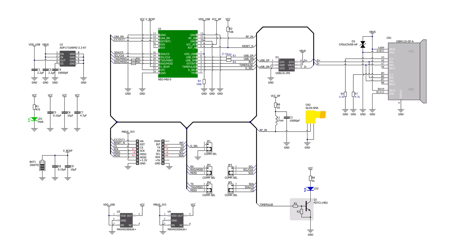
Click board™ Schematic
Step by step
Project assembly

Start by selecting your development board and Click board™. Begin with the Arduino UNO Rev3 as your development board.


Track your results in real time
Application Output
1. Application Output - In Debug mode, the 'Application Output' window enables real-time data monitoring, offering direct insight into execution results. Ensure proper data display by configuring the environment correctly using the provided tutorial.

2. UART Terminal - Use the UART Terminal to monitor data transmission via a USB to UART converter, allowing direct communication between the Click board™ and your development system. Configure the baud rate and other serial settings according to your project's requirements to ensure proper functionality. For step-by-step setup instructions, refer to the provided tutorial.

3. Plot Output - The Plot feature offers a powerful way to visualize real-time sensor data, enabling trend analysis, debugging, and comparison of multiple data points. To set it up correctly, follow the provided tutorial, which includes a step-by-step example of using the Plot feature to display Click board™ readings. To use the Plot feature in your code, use the function: plot(*insert_graph_name*, variable_name);. This is a general format, and it is up to the user to replace 'insert_graph_name' with the actual graph name and 'variable_name' with the parameter to be displayed.

Software Support
Library Description
This library contains API for GNSS 10 Click driver.
Key functions:
gnss10_reset_device- This function resets the device by toggling the RST pingnss10_generic_read- This function reads a desired number of data bytes from the modulegnss10_parse_gngga- This function parses the GNGGA data from the read response buffer
Open Source
Code example
The complete application code and a ready-to-use project are available through the NECTO Studio Package Manager for direct installation in the NECTO Studio. The application code can also be found on the MIKROE GitHub account.
/*!
 * @file main.c
 * @brief GNSS10 Click example
 *
 * # Description
 * This example demonstrates the use of GNSS 10 Click by reading and displaying
 * the GNSS coordinates.
 *
 * The demo application is composed of two sections :
 *
 * ## Application Init
 * Initializes the driver and resets the Click board.
 *
 * ## Application Task
 * Reads the received data, parses the GNGGA info from it, and once it receives the position fix
 * it will start displaying the coordinates on the USB UART.
 *
 * ## Additional Function
 * - static void gnss10_clear_app_buf ( void )
 * - static err_t gnss10_process ( gnss10_t *ctx )
 * - static void gnss10_parser_application ( char *rsp )
 *
 * @author Stefan Filipovic
 *
 */

#include "board.h"
#include "log.h"
#include "gnss10.h"

#define PROCESS_BUFFER_SIZE 200

static gnss10_t gnss10;
static log_t logger;

static char app_buf[ PROCESS_BUFFER_SIZE ] = { 0 };
static int32_t app_buf_len = 0;
static int32_t app_buf_cnt = 0;

/**
 * @brief GNSS 10 clearing application buffer.
 * @details This function clears memory of application buffer and reset its length and counter.
 * @return None.
 * @note None.
 */
static void gnss10_clear_app_buf ( void );

/**
 * @brief GNSS 10 data reading function.
 * @details This function reads data from device and concatenates data to application buffer.
 * @param[in] ctx : Click context object.
 * See #gnss10_t object definition for detailed explanation.
 * @return @li @c  0 - Read some data.
 *         @li @c -1 - Nothing is read or Application buffer overflow.
 * See #err_t definition for detailed explanation.
 * @note None.
 */
static err_t gnss10_process ( gnss10_t *ctx );

/**
 * @brief GNSS 10 parser application.
 * @param[in] rsp Response buffer.
 * @details This function logs GNSS data on the USB UART.
 * @return None.
 * @note None.
 */
static void gnss10_parser_application ( char *rsp );

void application_init ( void )
{
    log_cfg_t log_cfg;  /**< Logger config object. */
    gnss10_cfg_t gnss10_cfg;  /**< Click config object. */

    /**
     * Logger initialization.
     * Default baud rate: 115200
     * Default log level: LOG_LEVEL_DEBUG
     * @note If USB_UART_RX and USB_UART_TX
     * are defined as HAL_PIN_NC, you will
     * need to define them manually for log to work.
     * See @b LOG_MAP_USB_UART macro definition for detailed explanation.
     */
    LOG_MAP_USB_UART( log_cfg );
    log_init( &logger, &log_cfg );
    log_info( &logger, " Application Init " );

    // Click initialization.
    gnss10_cfg_setup( &gnss10_cfg );
    GNSS10_MAP_MIKROBUS( gnss10_cfg, MIKROBUS_1 );
    err_t init_flag = gnss10_init( &gnss10, &gnss10_cfg );
    if ( ( UART_ERROR == init_flag ) || ( I2C_MASTER_ERROR == init_flag ) || ( SPI_MASTER_ERROR == init_flag ) )
    {
        log_error( &logger, " Communication init." );
        for ( ; ; );
    }

    gnss10_reset_device ( &gnss10 );
    log_info( &logger, " Application Task " );
}

void application_task ( void )
{
    gnss10_process( &gnss10 );
    if ( app_buf_len > ( sizeof ( GNSS10_RSP_GNGGA ) + GNSS10_GNGGA_ELEMENT_SIZE ) )
    {
        gnss10_parser_application( app_buf );
    }
}

int main ( void )
{
    /* Do not remove this line or clock might not be set correctly. */
    #ifdef PREINIT_SUPPORTED
    preinit();
    #endif

    application_init( );

    for ( ; ; )
    {
        application_task( );
    }

    return 0;
}

static void gnss10_clear_app_buf ( void )
{
    memset( app_buf, 0, app_buf_len );
    app_buf_len = 0;
    app_buf_cnt = 0;
}

static err_t gnss10_process ( gnss10_t *ctx )
{
    int32_t rx_size = 0;
    char rx_buf[ PROCESS_BUFFER_SIZE ] = { 0 };
    if ( GNSS10_DRV_SEL_UART == ctx->drv_sel )
    {
        rx_size = gnss10_generic_read( ctx, rx_buf, PROCESS_BUFFER_SIZE );
    }
    else if ( ( GNSS10_DRV_SEL_I2C == ctx->drv_sel ) || ( GNSS10_DRV_SEL_SPI == ctx->drv_sel ) )
    {
        if ( GNSS10_OK == gnss10_generic_read( ctx, rx_buf, 1 ) )
        {
            if ( GNSS10_DUMMY != rx_buf[ 0 ] )
            {
                rx_size = 1;
            }
        }
    }
    if ( rx_size > 0 )
    {
        int32_t buf_cnt = 0;
        if ( app_buf_len + rx_size >= PROCESS_BUFFER_SIZE )
        {
            gnss10_clear_app_buf(  );
            return GNSS10_ERROR;
        }
        else
        {
            buf_cnt = app_buf_len;
            app_buf_len += rx_size;
        }
        for ( int32_t rx_cnt = 0; rx_cnt < rx_size; rx_cnt++ )
        {
            if ( rx_buf[ rx_cnt ] )
            {
                app_buf[ ( buf_cnt + rx_cnt ) ] = rx_buf[ rx_cnt ];
            }
            else
            {
                app_buf_len--;
                buf_cnt--;
            }
        }
        return GNSS10_OK;
    }
    return GNSS10_ERROR;
}

static void gnss10_parser_application ( char *rsp )
{
    char element_buf[ 100 ] = { 0 };
    if ( GNSS10_OK == gnss10_parse_gngga( rsp, GNSS10_GNGGA_LATITUDE, element_buf ) )
    {
        static uint8_t wait_for_fix_cnt = 0;
        if ( strlen( element_buf ) > 0 )
        {
            log_printf( &logger, "\r\n Latitude: %.2s degrees, %s minutes \r\n", element_buf, &element_buf[ 2 ] );
            gnss10_parse_gngga( rsp, GNSS10_GNGGA_LONGITUDE, element_buf );
            log_printf( &logger, " Longitude: %.3s degrees, %s minutes \r\n", element_buf, &element_buf[ 3 ] );
            memset( element_buf, 0, sizeof( element_buf ) );
            gnss10_parse_gngga( rsp, GNSS10_GNGGA_ALTITUDE, element_buf );
            log_printf( &logger, " Altitude: %s m \r\n", element_buf );
            wait_for_fix_cnt = 0;
        }
        else
        {
            if ( wait_for_fix_cnt % 5 == 0 )
            {
                log_printf( &logger, " Waiting for the position fix...\r\n\n" );
                wait_for_fix_cnt = 0;
            }
            wait_for_fix_cnt++;
        }
        gnss10_clear_app_buf(  );
    }
}

// ------------------------------------------------------------------------ END
Additional Support
Resources
Category:GPS/GNSS


