Navigate with ease with ATmega328P and L70
Your ultimate travel companion
Published Feb 14, 2024
Click board™
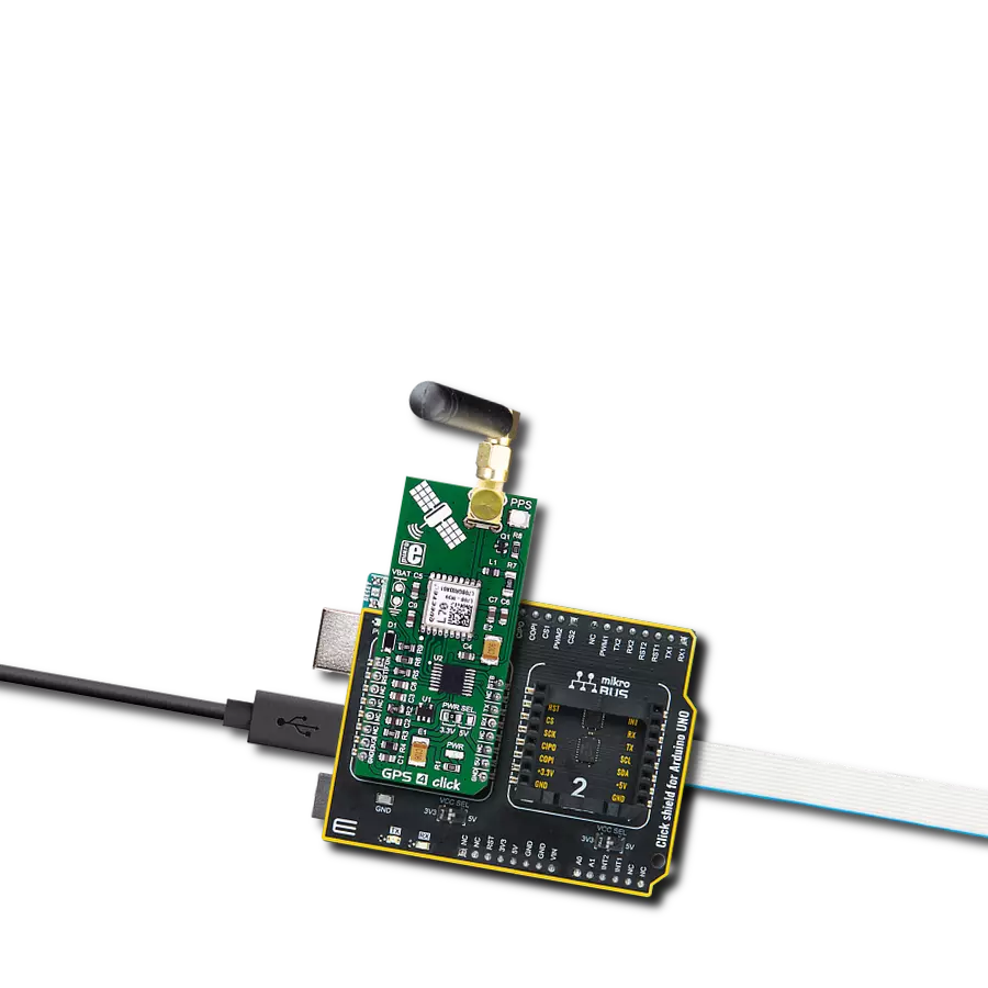
GPS 4 Click
Dev. board
Arduino UNO Rev3
Compiler
NECTO Studio
MCU
ATmega328P
Empower your journey and build intelligent navigation applications to simplify travel and enhance your experience
A
A
Hardware Overview
How does it work?
GPS 4 Click is based on the L70, a compact GPS module from Quectel. The click is designed to run on either a 3.3V or 5V power supply. It communicates with the target microcontroller over the UART interface, with additional functionality provided by the following pins on the mikroBUS™ line: PWM, AN, RST. The L70, an SMD-type module, brings the high performance of the MTK positioning engine to industrial applications with a compact profile, ultra-low power consumption, and fast positioning capability. Combining advanced AGPS called EASY™ (Embedded Assist System) and proven AlwaysLocate™ technology, L70 achieves the highest performance and fully meets the industrial standard. EASY™ technology ensures
L70 can calculate and predict orbits automatically using the ephemeris data (up to 3 days) stored in internal RAM so that L70 can fix position quickly even at indoor signal levels with low power consumption. With AlwaysLocate™ technology, L70 can adaptively adjust the on/off time to balance positioning accuracy and power consumption according to the environmental and motion conditions. A constellation of satellites sends a continuous signal towards Earth. Onboard every satellite is an atomic clock, and all of them are synchronized, thanks to a reference time scale defined by the whole system. So, the signals from the different satellites of the same constellation share the same reference time scale. The user wanting to use GPS to determine its position
must have an antenna that receives the signals from the satellites and a receiver that translates them. The antenna position will be deduced from the measurements of the time delay between the emission time (satellite) and the reception time (receiver) for at least four signals coming from different satellites. This Click board™ can operate with either 3.3V or 5V logic voltage levels selected via the PWR SEL jumper. This way, both 3.3V and 5V capable MCUs can use the communication lines properly. Also, this Click board™ comes equipped with a library containing easy-to-use functions and an example code that can be used as a reference for further development.

Features overview
Development board
Arduino UNO is a versatile microcontroller board built around the ATmega328P chip. It offers extensive connectivity options for various projects, featuring 14 digital input/output pins, six of which are PWM-capable, along with six analog inputs. Its core components include a 16MHz ceramic resonator, a USB connection, a power jack, an
ICSP header, and a reset button, providing everything necessary to power and program the board. The Uno is ready to go, whether connected to a computer via USB or powered by an AC-to-DC adapter or battery. As the first USB Arduino board, it serves as the benchmark for the Arduino platform, with "Uno" symbolizing its status as the
first in a series. This name choice, meaning "one" in Italian, commemorates the launch of Arduino Software (IDE) 1.0. Initially introduced alongside version 1.0 of the Arduino Software (IDE), the Uno has since become the foundational model for subsequent Arduino releases, embodying the platform's evolution.

Microcontroller Overview
MCU Card / MCU

Architecture
AVR
MCU Memory (KB)
32
Silicon Vendor
Microchip
Pin count
28
RAM (Bytes)
2048
You complete me!
Accessories
Click Shield for Arduino UNO has two proprietary mikroBUS™ sockets, allowing all the Click board™ devices to be interfaced with the Arduino UNO board without effort. The Arduino Uno, a microcontroller board based on the ATmega328P, provides an affordable and flexible way for users to try out new concepts and build prototypes with the ATmega328P microcontroller from various combinations of performance, power consumption, and features. The Arduino Uno has 14 digital input/output pins (of which six can be used as PWM outputs), six analog inputs, a 16 MHz ceramic resonator (CSTCE16M0V53-R0), a USB connection, a power jack, an ICSP header, and reset button. Most of the ATmega328P microcontroller pins are brought to the IO pins on the left and right edge of the board, which are then connected to two existing mikroBUS™ sockets. This Click Shield also has several switches that perform functions such as selecting the logic levels of analog signals on mikroBUS™ sockets and selecting logic voltage levels of the mikroBUS™ sockets themselves. Besides, the user is offered the possibility of using any Click board™ with the help of existing bidirectional level-shifting voltage translators, regardless of whether the Click board™ operates at a 3.3V or 5V logic voltage level. Once you connect the Arduino UNO board with our Click Shield for Arduino UNO, you can access hundreds of Click boards™, working with 3.3V or 5V logic voltage levels.

Rubber Antenna GSM/GPRS Right Angle is the perfect companion for all GSM Click boards™ in our extensive lineup. This specialized antenna is designed to optimize your wireless connectivity with impressive features. With a wide frequency range spanning 824-894/1710-1990MHz or 890-960/1710-1890MHz, it can handle various frequency bands, ensuring a seamless and reliable connection. The antenna boasts an impedance of 50 Ohms and a gain of 2dB, enhancing signal reception and transmission. Its 70/180MHz bandwidth provides flexibility for diverse applications. The vertical polarization further enhances its performance. With a maximum input power capacity of 50W, this antenna ensures robust communication even under demanding conditions. Measuring a compact 50mm in length and featuring an SMA male connector, the Rubber Antenna GSM/GPRS Right Angle is a versatile and compact solution for your wireless communication needs.

Used MCU Pins
mikroBUS™ mapper
Take a closer look
Click board™ Schematic

Step by step
Project assembly

Start by selecting your development board and Click board™. Begin with the Arduino UNO Rev3 as your development board.


Software Support
Library Description
This library contains API for GPS 4 Click driver.
Key functions:
gps4_generic_parser- Generic parser functiongps4_generic_read- Generic read functiongps4_module_wakeup- Wake-up module
Open Source
Code example
The complete application code and a ready-to-use project are available through the NECTO Studio Package Manager for direct installation in the NECTO Studio. The application code can also be found on the MIKROE GitHub account.
/*!
 * \file
 * \brief Gps4 Click example
 *
 * # Description
 * This example reads and processes data from GPS4 Clicks.
 *
 * The demo application is composed of two sections :
 *
 * ## Application Init
 * Initializes driver and wake-up module.
 *
 * ## Application Task
 * Reads the received data and parses it.
 *
 * ## Additional Function
 * - gps4_process ( ) - The general process of collecting data the module sends.
 *
 *
 * \author MikroE Team
 *
 */
// ------------------------------------------------------------------- INCLUDES

#include "board.h"
#include "log.h"
#include "gps4.h"
#include "string.h"

#define PROCESS_COUNTER 15
#define PROCESS_RX_BUFFER_SIZE 600
#define PROCESS_PARSER_BUFFER_SIZE 600

// ------------------------------------------------------------------ VARIABLES

static gps4_t gps4;
static log_t logger;

static char current_parser_buf[ PROCESS_PARSER_BUFFER_SIZE ];

// ------------------------------------------------------- ADDITIONAL FUNCTIONS

static void gps4_process ( void )
{
    int32_t rsp_size;
    uint16_t rsp_cnt = 0;

    char uart_rx_buffer[ PROCESS_RX_BUFFER_SIZE ] = { 0 };
    uint16_t check_buf_cnt;
    uint8_t process_cnt = PROCESS_COUNTER;

    // Clear parser buffer
    memset( current_parser_buf, 0 , PROCESS_PARSER_BUFFER_SIZE );

    while( process_cnt != 0 )
    {
        rsp_size = gps4_generic_read( &gps4, &uart_rx_buffer, PROCESS_RX_BUFFER_SIZE );

        if ( rsp_size > 0 )
        {
            // Validation of the received data
            for ( check_buf_cnt = 0; check_buf_cnt < rsp_size; check_buf_cnt++ )
            {
                if ( uart_rx_buffer[ check_buf_cnt ] == 0 )
                {
                    uart_rx_buffer[ check_buf_cnt ] = 13;
                }
            }

            // Storages data in parser buffer
            rsp_cnt += rsp_size;
            if ( rsp_cnt < PROCESS_PARSER_BUFFER_SIZE )
            {
                strncat( current_parser_buf, uart_rx_buffer, rsp_size );
            }
            // Clear RX buffer
            memset( uart_rx_buffer, 0, PROCESS_RX_BUFFER_SIZE );
        }
        else
        {
            process_cnt--;

            // Process delay
            Delay_100ms( );
        }
    }
}

static void parser_application ( char *rsp )
{
    char element_buf[ 200 ] = { 0 };

    log_printf( &logger, "\r\n-----------------------\r\n" );
    gps4_generic_parser( rsp, GPS4_NEMA_GPGGA, GPS4_GPGGA_LATITUDE, element_buf );
    if ( strlen( element_buf ) > 0 )
    {
        log_printf( &logger, "Latitude:  %.2s degrees, %s minutes \r\n", element_buf, &element_buf[ 2 ] );
        gps4_generic_parser( rsp, GPS4_NEMA_GPGGA, GPS4_GPGGA_LONGITUDE, element_buf );
        log_printf( &logger, "Longitude:  %.3s degrees, %s minutes \r\n", element_buf, &element_buf[ 3 ] );
        memset( element_buf, 0, sizeof( element_buf ) );
        gps4_generic_parser( rsp, GPS4_NEMA_GPGGA, GPS4_GPGGA_ALTITUDE, element_buf );
        log_printf( &logger, "Altitude: %s m", element_buf );
    }
    else
    {
        log_printf( &logger, "Waiting for the position fix..." );
    }
}

// ------------------------------------------------------ APPLICATION FUNCTIONS

void application_init ( void )
{
    log_cfg_t log_cfg;
    gps4_cfg_t cfg;

    /**
     * Logger initialization.
     * Default baud rate: 115200
     * Default log level: LOG_LEVEL_DEBUG
     * @note If USB_UART_RX and USB_UART_TX
     * are defined as HAL_PIN_NC, you will
     * need to define them manually for log to work.
     * See @b LOG_MAP_USB_UART macro definition for detailed explanation.
     */
    LOG_MAP_USB_UART( log_cfg );
    log_init( &logger, &log_cfg );
    log_info( &logger, "---- Application Init ----" );

    //  Click initialization.

    gps4_cfg_setup( &cfg );
    GPS4_MAP_MIKROBUS( cfg, MIKROBUS_1 );
    gps4_init( &gps4, &cfg );

    gps4_module_wakeup( &gps4 );
    Delay_ms ( 1000 );
    Delay_ms ( 1000 );
    Delay_ms ( 1000 );
    Delay_ms ( 1000 );
    Delay_ms ( 1000 );
}

void application_task ( void )
{
    gps4_process(  );
    parser_application( current_parser_buf );
}

int main ( void )
{
    /* Do not remove this line or clock might not be set correctly. */
    #ifdef PREINIT_SUPPORTED
    preinit();
    #endif

    application_init( );

    for ( ; ; )
    {
        application_task( );
    }

    return 0;
}


// ------------------------------------------------------------------------ END
Additional Support
Resources
Category:GPS/GNSS


