Make interactions more intuitive and responsive with Si1143 and ATmega328P
Where your presence sparks action

Published Feb 14, 2024
Click board™
Proximity 10 Click
Dev. board
Arduino UNO Rev3
Compiler
NECTO Studio
MCU
ATmega328P
We're dedicated to making proximity technology accessible and impactful, shaping the future of human-machine interaction
A
A
Hardware Overview
How does it work?
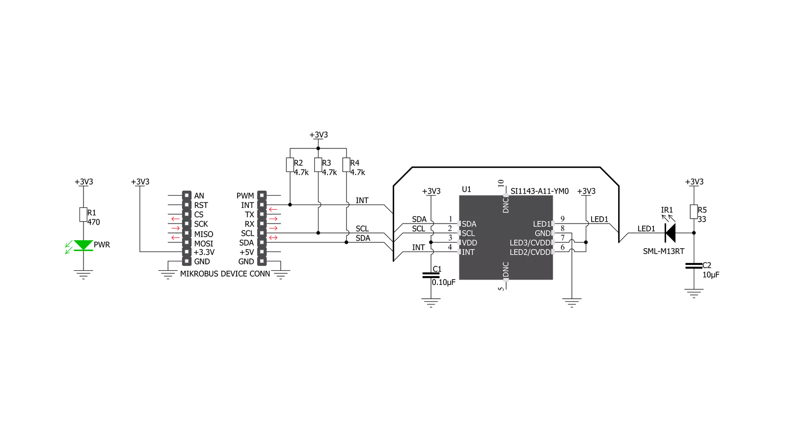
Proximity 10 Click is based on the SI1143, a photometric sensor for the ambient light and proximity detection from Silicon Labs. Among other sections, this IC contains a LED driver, used to drive an externally connected LED, which provides feedback for the SI1143 sensory sections. Therefore, the LED should be chosen so that its spectrum matches the spectral sensitivity of the on-chip light sensor. For this reason, the Click board™ is equipped with the narrow beam LED from Rohm Semiconductor with its spectral response characteristic peaking at 870nm, which is a perfect choice for this application. The proximity detection consists of sending a pulse to the LED while measuring the response of the reflected light. Most of the parameters are user configurable, such as the sampling frequency,
pulses duration, averaging parameters and more. More in-depth information about the registers can be found in the SI1143 datasheet. Aimed towards the low consumption market, the SI1143 uses a rather low voltage range, between 1.7V and 3.6V. Since the most of the MCUs use 3.3V, this click board™ is designed so that the SI1143 IC is directly interfaced with the mikroBUS™. Proximity 10 click offers an interrupt output pin that can be used to trigger an interrupt on the host MCU. The SI1143 IC interrupt engine allows several interrupt sources, which can be used to trigger a state change on the INT pin. These sources include proximity detection interrupts (proximity OFF and proximity ON), sample interrupts, and more. The INT pin itself is highly configurable, and when asserted, this pin triggers an MCU interrupt, informing it
that the configured interrupt event has occurred. The MCU can then read the desired register output, not having to poll it constantly, which saves both MCU cycles and power. The INT pin is routed via the level shifting IC to the mikroBUS™ INT pin. As already mentioned, detailed information on the SI1143 IC registers can be found in the datasheet. However, MikroElektronika provides a library that contains functions compatible with the MikroElektronika compilers, which can be used for simplified programming of the Proximity 10 click. The library also contains an example application, which demonstrates its use. This example application can be used as a reference for custom designs.


Features overview
Development board
Arduino UNO is a versatile microcontroller board built around the ATmega328P chip. It offers extensive connectivity options for various projects, featuring 14 digital input/output pins, six of which are PWM-capable, along with six analog inputs. Its core components include a 16MHz ceramic resonator, a USB connection, a power jack, an
ICSP header, and a reset button, providing everything necessary to power and program the board. The Uno is ready to go, whether connected to a computer via USB or powered by an AC-to-DC adapter or battery. As the first USB Arduino board, it serves as the benchmark for the Arduino platform, with "Uno" symbolizing its status as the
first in a series. This name choice, meaning "one" in Italian, commemorates the launch of Arduino Software (IDE) 1.0. Initially introduced alongside version 1.0 of the Arduino Software (IDE), the Uno has since become the foundational model for subsequent Arduino releases, embodying the platform's evolution.

Microcontroller Overview
MCU Card / MCU

Architecture
AVR
MCU Memory (KB)
32
Silicon Vendor
Microchip
Pin count
28
RAM (Bytes)
2048
You complete me!
Accessories
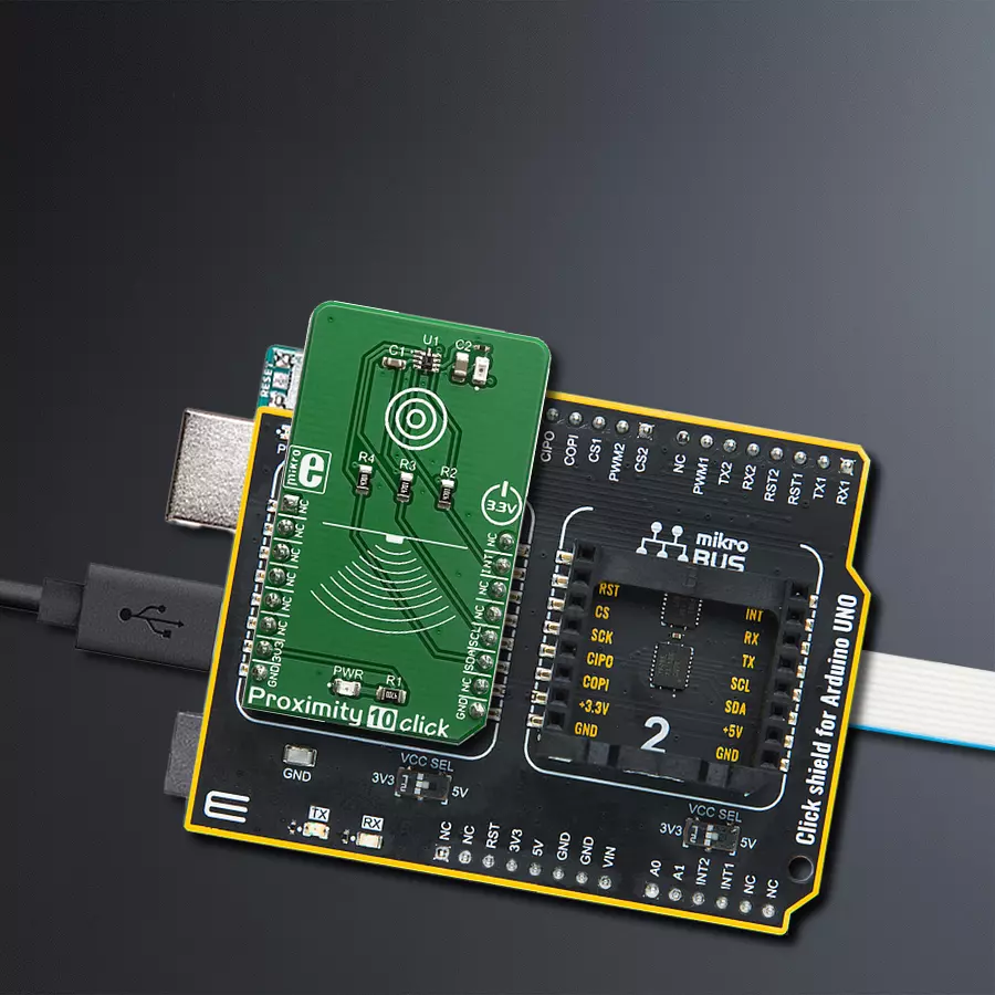
Click Shield for Arduino UNO has two proprietary mikroBUS™ sockets, allowing all the Click board™ devices to be interfaced with the Arduino UNO board without effort. The Arduino Uno, a microcontroller board based on the ATmega328P, provides an affordable and flexible way for users to try out new concepts and build prototypes with the ATmega328P microcontroller from various combinations of performance, power consumption, and features. The Arduino Uno has 14 digital input/output pins (of which six can be used as PWM outputs), six analog inputs, a 16 MHz ceramic resonator (CSTCE16M0V53-R0), a USB connection, a power jack, an ICSP header, and reset button. Most of the ATmega328P microcontroller pins are brought to the IO pins on the left and right edge of the board, which are then connected to two existing mikroBUS™ sockets. This Click Shield also has several switches that perform functions such as selecting the logic levels of analog signals on mikroBUS™ sockets and selecting logic voltage levels of the mikroBUS™ sockets themselves. Besides, the user is offered the possibility of using any Click board™ with the help of existing bidirectional level-shifting voltage translators, regardless of whether the Click board™ operates at a 3.3V or 5V logic voltage level. Once you connect the Arduino UNO board with our Click Shield for Arduino UNO, you can access hundreds of Click boards™, working with 3.3V or 5V logic voltage levels.

Used MCU Pins
mikroBUS™ mapper
Take a closer look
Click board™ Schematic
Step by step
Project assembly

Start by selecting your development board and Click board™. Begin with the Arduino UNO Rev3 as your development board.


Software Support
Library Description
This library contains API for Proximity 10 Click driver.
Key functions:
proximity10_check_int_status- This function checks the desired interrupt flags status.proximity10_send_command- This function allows user to execute a desired command and checks the response.proximity10_param_set- This function sets the selected parameter to the desired value, and checks the response.
Open Source
Code example
The complete application code and a ready-to-use project are available through the NECTO Studio Package Manager for direct installation in the NECTO Studio. The application code can also be found on the MIKROE GitHub account.
/*!
 * \file
 * \brief Proximity10 Click example
 *
 * # Description
 * This application enables proximity sensor to detect objects from distance up to 20cm.
 *
 * The demo application is composed of two sections :
 *
 * ## Application Init
 * Initializes I2C serial interface and performs a device wake up, reset and
 * all necessary configurations.
 * The device will wake up and performs measurements every 10 milliseconds.
 *
 * ## Application Task
 * Reads the proximity PS1 data value and sends result to the uart terminal.
 * If measured proximity value is greater than selected proximity threshold value, the interrupt will be generated and
 * the message will be showed on the uart terminal.
 * When interrupt is generated the Sound function will make an alarm sound with determined duration depending on the detected proximity value,
 * how much is object away or close from the sensor.
 *
 * *note:*
 * Additional Functions :
 * - checkResponse - Sends an error code message to the uart terminal if error code is detected in the response.
 *
 * \author MikroE Team
 *
 */
// ------------------------------------------------------------------- INCLUDES

#include "board.h"
#include "log.h"
#include "proximity10.h"

// ------------------------------------------------------------------ VARIABLES

static proximity10_t proximity10;
static log_t logger;

// ------------------------------------------------------- ADDITIONAL FUNCTIONS

void check_response ( uint8_t cmd_resp )
{
    switch ( cmd_resp )
    {
        case PROXIMITY10_INVALID_CMD_ENCOUNT :
        {
            log_printf( &logger, "** Invalid Command Encountered during command processing **\r\n" );
            break;
        }
        case PROXIMITY10_ADC_OVRFLOW_ENCOUNT_PS1 :
        {
            log_printf( &logger, "** ADC Overflow Encountered during PS1 measurement **\r\n" );
            break;
        }
        case PROXIMITY10_ADC_OVRFLOW_ENCOUNT_PS2 :
        {
            log_printf( &logger, "** ADC Overflow Encountered during PS2 measurement **\r\n" );
            break;
        }
        case PROXIMITY10_ADC_OVRFLOW_ENCOUNT_PS3 :
        {
            log_printf( &logger, "** ADC Overflow Encountered during PS3 measurement **\r\n" );
            break;
        }
        case PROXIMITY10_ADC_OVRFLOW_ENCOUNT_ALS_VIS :
        {
            log_printf( &logger, "** ADC Overflow Encountered during ALS-VIS measurement **\r\n" );
            break;
        }
        case PROXIMITY10_ADC_OVRFLOW_ENCOUNT_ALS_IR :
        {
            log_printf( &logger, "** ADC Overflow Encountered during ALS-IR measurement **\r\n" );
            break;
        }
        case PROXIMITY10_ADC_OVRFLOW_ENCOUNT_AUX :
        {
            log_printf( &logger, "** ADC Overflow Encountered during AUX measurement **\r\n" );
            break;
        }
        default :
        {
            break;
        }
    }
}

// ------------------------------------------------------ APPLICATION FUNCTIONS

void application_init ( void )
{
    log_cfg_t log_cfg;
    proximity10_cfg_t cfg;

    uint8_t w_temp;
    uint8_t cmd_resp;

    /**
     * Logger initialization.
     * Default baud rate: 115200
     * Default log level: LOG_LEVEL_DEBUG
     * @note If USB_UART_RX and USB_UART_TX
     * are defined as HAL_PIN_NC, you will
     * need to define them manually for log to work.
     * See @b LOG_MAP_USB_UART macro definition for detailed explanation.
     */
    LOG_MAP_USB_UART( log_cfg );
    log_init( &logger, &log_cfg );
    log_info( &logger, "---- Application Init ----" );

    //  Click initialization.

    proximity10_cfg_setup( &cfg );
    PROXIMITY10_MAP_MIKROBUS( cfg, MIKROBUS_1 );
    proximity10_init( &proximity10, &cfg );

    Delay_ms ( 1000 );
    Delay_ms ( 1000 );

    w_temp = PROXIMITY10_HW_KEY;
    proximity10_generic_write( &proximity10, PROXIMITY10_HW_KEY_REG, &w_temp, 1 );

    cmd_resp = proximity10_send_command( &proximity10, PROXIMITY10_NOP_CMD );
    check_response( cmd_resp );
    cmd_resp = proximity10_send_command( &proximity10, PROXIMITY10_RESET_CMD );
    check_response( cmd_resp );
    Delay_ms ( 1000 );
    Delay_ms ( 1000 );

    cmd_resp = proximity10_param_set( &proximity10, PROXIMITY10_CHLIST_PARAM, PROXIMITY10_EN_AUX | PROXIMITY10_EN_ALS_IR | PROXIMITY10_EN_ALS_VIS | PROXIMITY10_EN_PS1 );
    check_response( cmd_resp );
    cmd_resp = proximity10_param_set( &proximity10, PROXIMITY10_PSLED12_SEL_PARAM, PROXIMITY10_LED1_DRIVE_EN );
    check_response( cmd_resp );
    cmd_resp = proximity10_param_set( &proximity10, PROXIMITY10_PS_ADC_MISC_PARAM, PROXIMITY10_NORMAL_SIGNAL_RANGE | PROXIMITY10_NORMAL_PROX_MEAS_MODE );
    check_response( cmd_resp );
    cmd_resp = proximity10_param_set( &proximity10, PROXIMITY10_PS_ADC_GAIN_PARAM, PROXIMITY10_ADC_CLOCK_DIV_4 );
    check_response( cmd_resp );

    proximity10_default_cfg ( &proximity10 );

    cmd_resp = proximity10_send_command( &proximity10, PROXIMITY10_PS_AUTO_CMD );
    check_response( cmd_resp );

    //Sound_Init( &GPIOE_ODR, 14 );

    log_printf( &logger, "** Proximity 10 is initialized **\r\n" );
    log_printf( &logger, "**************************************\r\n" );
    Delay_ms ( 1000 );
}

void application_task ( void )
{
    //  Task implementation.

    uint32_t proximity;
    uint8_t temp_read[ 2 ];
    uint8_t int_status;
    uint16_t alarm_dur;

    proximity10_generic_read( &proximity10, PROXIMITY10_PS1_DATA_REG, &temp_read, 2 );
    proximity = temp_read[ 1 ];
    proximity <<= 8;
    proximity |= temp_read[ 0 ];

    log_printf( &logger, "** Proximity PS1 : %u \r\n", proximity );

    int_status = proximity10_check_int_status( &proximity10, PROXIMITY10_PS1_INT_FLAG, PROXIMITY10_INT_CLEAR_DIS );

    if ( int_status == PROXIMITY10_PS1_INT_FLAG )
    {
        log_printf( &logger, "** Object is detected **\r\n" );

        alarm_dur = proximity / 100;
        alarm_dur = alarm_dur + 35;
        alarm_dur = ( float )( alarm_dur * 0.30928 );
        alarm_dur = 180 - alarm_dur;

        //Sound_Play( 1400, alarm_dur );
        Delay_ms ( 1000 );
    }
    else
    {
        Delay_ms ( 1000 );
    }
    log_printf( &logger, "**************************************\r\n" );
}

int main ( void )
{
    /* Do not remove this line or clock might not be set correctly. */
    #ifdef PREINIT_SUPPORTED
    preinit();
    #endif

    application_init( );

    for ( ; ; )
    {
        application_task( );
    }

    return 0;
}


// ------------------------------------------------------------------------ END
Additional Support
Resources
Category:Proximity


