Extend your project's battery life with TPS61299 and ATmega328
Synchronous boost converter
Published May 06, 2024
Click board™
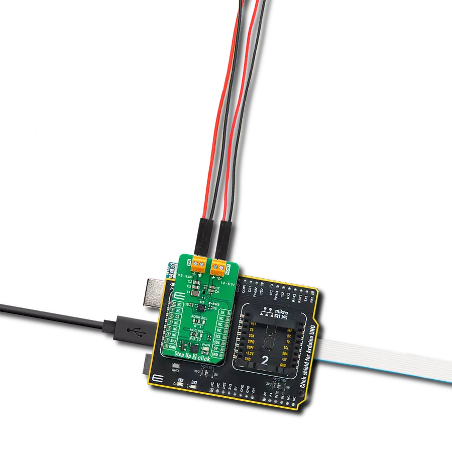
Step Up 2 Click
Dev. board
Arduino UNO Rev3
Compiler
NECTO Studio
MCU
ATmega328
Increase battery life for portable devices by boosting voltage from low-power sources.
A
A
Hardware Overview
How does it work?
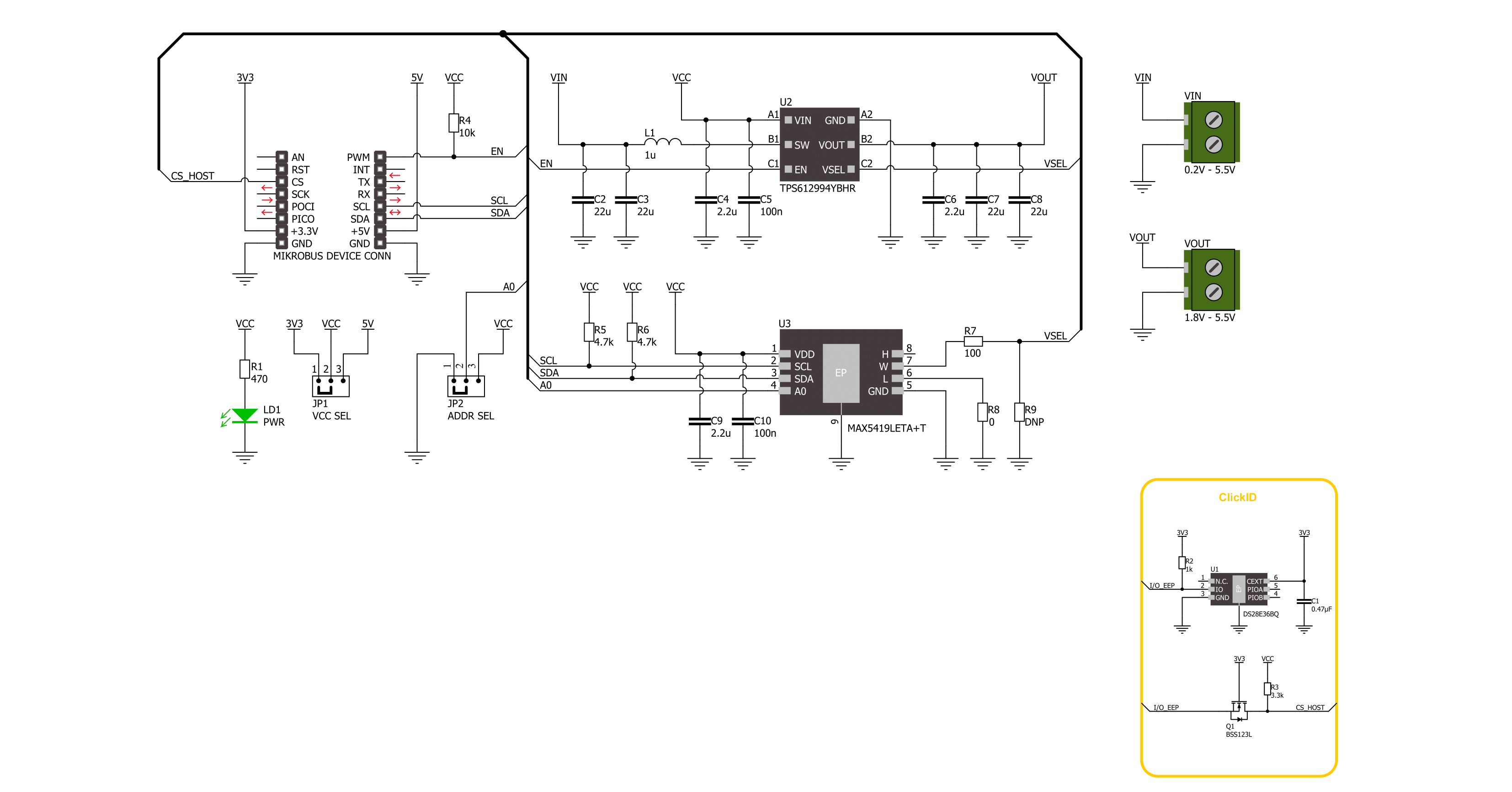
Step Up 2 Click is based on the TPS61299, a synchronous boost converter with an exceptionally low quiescent current from Texas Instruments. It is designed to provide efficient power solutions for devices powered by alkaline or coin cell batteries, boasting high efficiency even under light-load conditions to extend operational time. This component also stands out for its additional current limit functionality, ensuring optimal performance and reliability. With the ability to operate by simply using the EN pin from the mikroBUS™ socket for
device enablement - a high logic signal activates the device, whereas a low logic signal deactivates it - this boost converter exemplifies efficiency and ease of use. The Step Up 2 Click also integrates the MAX5419, a digital potentiometer from Analog Devices, for precise output voltage adjustments, as well as an ADDR SEL jumper. This jumper allows for seamless selection of the I2C address of the MAX5419, leveraging the I2C interface for meticulous control. Supplying an external voltage range from 0.2V to 5.5V via the VIN terminal, the
board offers a regulated output voltage range from 1.8V to 5.5V at the VOUT terminal - adjustable through digital potentiometer configuration. This Click board™ can operate with either 3.3V or 5V logic voltage levels selected via the VCC SEL jumper. This way, both 3.3V and 5V capable MCUs can use the communication lines properly. Also, this Click board™ comes equipped with a library containing easy-to-use functions and an example code that can be used as a reference for further development.

Features overview
Development board
Arduino UNO is a versatile microcontroller board built around the ATmega328P chip. It offers extensive connectivity options for various projects, featuring 14 digital input/output pins, six of which are PWM-capable, along with six analog inputs. Its core components include a 16MHz ceramic resonator, a USB connection, a power jack, an
ICSP header, and a reset button, providing everything necessary to power and program the board. The Uno is ready to go, whether connected to a computer via USB or powered by an AC-to-DC adapter or battery. As the first USB Arduino board, it serves as the benchmark for the Arduino platform, with "Uno" symbolizing its status as the
first in a series. This name choice, meaning "one" in Italian, commemorates the launch of Arduino Software (IDE) 1.0. Initially introduced alongside version 1.0 of the Arduino Software (IDE), the Uno has since become the foundational model for subsequent Arduino releases, embodying the platform's evolution.

Microcontroller Overview
MCU Card / MCU

Architecture
AVR
MCU Memory (KB)
32
Silicon Vendor
Microchip
Pin count
32
RAM (Bytes)
2048
You complete me!
Accessories
Click Shield for Arduino UNO has two proprietary mikroBUS™ sockets, allowing all the Click board™ devices to be interfaced with the Arduino UNO board without effort. The Arduino Uno, a microcontroller board based on the ATmega328P, provides an affordable and flexible way for users to try out new concepts and build prototypes with the ATmega328P microcontroller from various combinations of performance, power consumption, and features. The Arduino Uno has 14 digital input/output pins (of which six can be used as PWM outputs), six analog inputs, a 16 MHz ceramic resonator (CSTCE16M0V53-R0), a USB connection, a power jack, an ICSP header, and reset button. Most of the ATmega328P microcontroller pins are brought to the IO pins on the left and right edge of the board, which are then connected to two existing mikroBUS™ sockets. This Click Shield also has several switches that perform functions such as selecting the logic levels of analog signals on mikroBUS™ sockets and selecting logic voltage levels of the mikroBUS™ sockets themselves. Besides, the user is offered the possibility of using any Click board™ with the help of existing bidirectional level-shifting voltage translators, regardless of whether the Click board™ operates at a 3.3V or 5V logic voltage level. Once you connect the Arduino UNO board with our Click Shield for Arduino UNO, you can access hundreds of Click boards™, working with 3.3V or 5V logic voltage levels.

Used MCU Pins
mikroBUS™ mapper
Take a closer look
Click board™ Schematic
Step by step
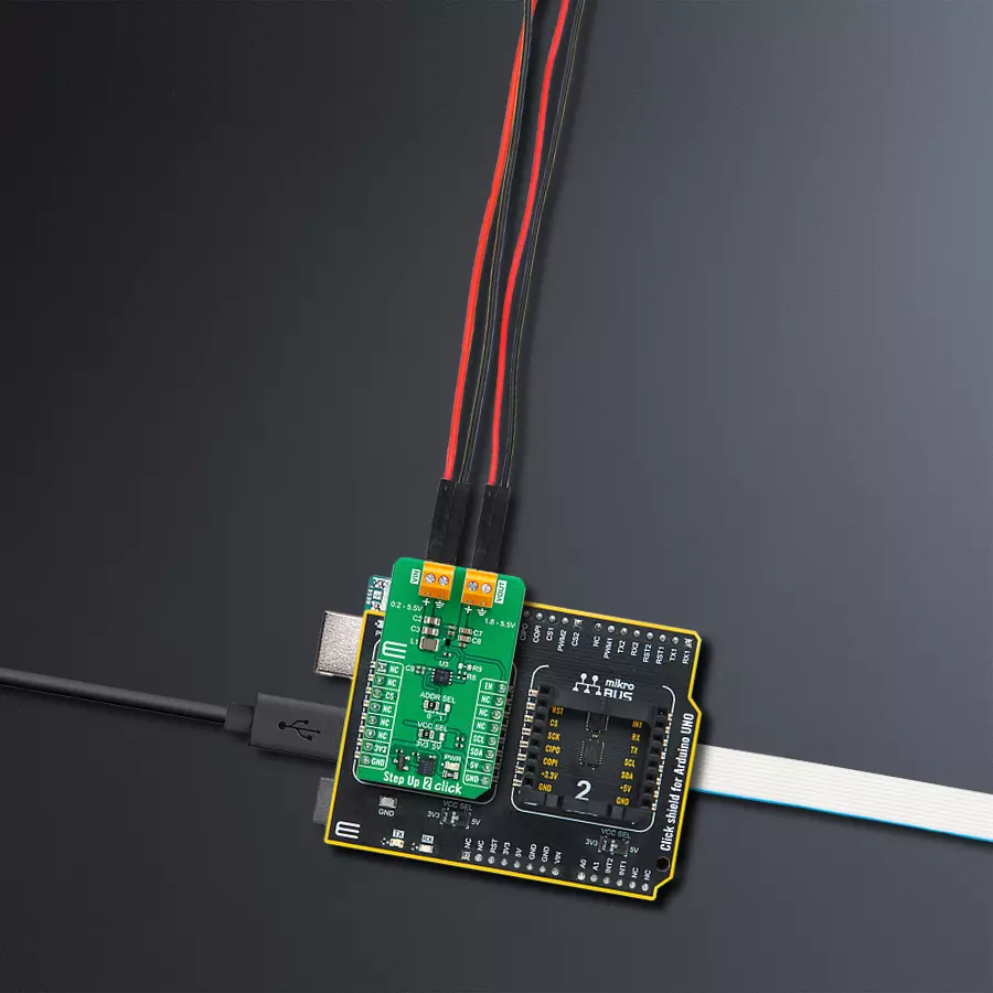
Project assembly

Start by selecting your development board and Click board™. Begin with the Arduino UNO Rev3 as your development board.


Track your results in real time
Application Output
1. Application Output - In Debug mode, the 'Application Output' window enables real-time data monitoring, offering direct insight into execution results. Ensure proper data display by configuring the environment correctly using the provided tutorial.

2. UART Terminal - Use the UART Terminal to monitor data transmission via a USB to UART converter, allowing direct communication between the Click board™ and your development system. Configure the baud rate and other serial settings according to your project's requirements to ensure proper functionality. For step-by-step setup instructions, refer to the provided tutorial.

3. Plot Output - The Plot feature offers a powerful way to visualize real-time sensor data, enabling trend analysis, debugging, and comparison of multiple data points. To set it up correctly, follow the provided tutorial, which includes a step-by-step example of using the Plot feature to display Click board™ readings. To use the Plot feature in your code, use the function: plot(*insert_graph_name*, variable_name);. This is a general format, and it is up to the user to replace 'insert_graph_name' with the actual graph name and 'variable_name' with the parameter to be displayed.

Software Support
Library Description
This library contains API for Step Up 2 Click driver.
Key functions:
stepup2_set_vout- This function sets the voltage output level.stepup2_set_resistance- This function sets a desired resistance by writing to the volatile memory register and the wiper position.stepup2_enable- This function turns on the power switch and enables the boost mode.
Open Source
Code example
The complete application code and a ready-to-use project are available through the NECTO Studio Package Manager for direct installation in the NECTO Studio. The application code can also be found on the MIKROE GitHub account.
/*!
 * @file main.c
 * @brief Step Up 2 Click example
 *
 * # Description
 * This example demonstrates the use of the Step Up 2 Click board by changing the output voltage.
 *
 * The demo application is composed of two sections :
 *
 * ## Application Init
 * Initialization of I2C module and log UART.
 * After driver initialization, the app executes a default configuration.
 *
 * ## Application Task
 * The demo application changes the output voltage and displays the current voltage output value.
 * Results are being sent to the UART Terminal, where you can track their changes.
 *
 * @author Nenad Filipovic
 *
 */

#include "board.h"
#include "log.h"
#include "stepup2.h"

static stepup2_t stepup2;
static log_t logger;

void application_init ( void )
{
    log_cfg_t log_cfg;  /**< Logger config object. */
    stepup2_cfg_t stepup2_cfg;  /**< Click config object. */

    /**
     * Logger initialization.
     * Default baud rate: 115200
     * Default log level: LOG_LEVEL_DEBUG
     * @note If USB_UART_RX and USB_UART_TX
     * are defined as HAL_PIN_NC, you will
     * need to define them manually for log to work.
     * See @b LOG_MAP_USB_UART macro definition for detailed explanation.
     */
    LOG_MAP_USB_UART( log_cfg );
    log_init( &logger, &log_cfg );
    log_info( &logger, " Application Init " );

    // Click initialization.
    stepup2_cfg_setup( &stepup2_cfg );
    STEPUP2_MAP_MIKROBUS( stepup2_cfg, MIKROBUS_1 );
    if ( I2C_MASTER_ERROR == stepup2_init( &stepup2, &stepup2_cfg ) )
    {
        log_error( &logger, " Communication init." );
        for ( ; ; );
    }

    if ( STEPUP2_ERROR == stepup2_default_cfg ( &stepup2 ) )
    {
        log_error( &logger, " Default configuration." );
        for ( ; ; );
    }

    log_info( &logger, " Application Task " );
}

void application_task ( void )
{
    float vout_table[ 15 ] = { STEPUP2_VOUT_LIST };
    for ( stepup2_vout_t vout = STEPUP2_VOUT_5V5; vout <= STEPUP2_VOUT_3V3; vout++ )
    {
        if ( STEPUP2_OK == stepup2_set_vout( &stepup2, vout ) )
        {
            log_printf( &logger, " Voltage: %.2f[V]\r\n\n", vout_table[ vout ] );
            Delay_ms ( 1000 );
            Delay_ms ( 1000 );
            Delay_ms ( 1000 );
            Delay_ms ( 1000 );
            Delay_ms ( 1000 );
        }
    }
}

int main ( void )
{
    /* Do not remove this line or clock might not be set correctly. */
    #ifdef PREINIT_SUPPORTED
    preinit();
    #endif

    application_init( );

    for ( ; ; )
    {
        application_task( );
    }

    return 0;
}

// ------------------------------------------------------------------------ END
Additional Support
Resources
Category:Boost