From void to innovation with MPXV6115V and ATmega328P
Unlocking potential in empty spaces

Published Feb 14, 2024
Click board™
Vacuum Click
Dev Board
Arduino UNO Rev3
Compiler
NECTO Studio
MCU
ATmega328P
The ultimate tool for vacuum experiments, our pressure sensor empowers researchers and engineers to explore new frontiers in science and technology, providing critical data with unmatched precision
A
A
Hardware Overview
How does it work?
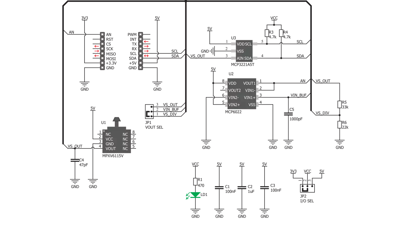
Vacuum Click is based on the MPXV6115V, a highly advanced monolithic vacuum pressure sensor from NXP. This sensor features the piezo-resistive MEMS sensing element, combined with the application-specific integrated circuit (ASIC) allowing a high degree of linearity, as well as a very low drift over the temperature. The lower part of the sensor contains the necessary sensing elements, while the upper part of the sensor is shaped as a small tube, and it is referred to as "port" in the datasheet. A small rubberized hose can easily be attached to the inlet, so that the vacuum producing counterpart can be securely connected with the sensor. The design of the inlet prevents leakage that might appear if the sealing is not good enough. The sensor itself outputs approximately 4.6V DC voltage on its output pin when it is located at the sea-level pressure. As the pressure decreases, the voltage drops towards 0V. The ASIC ensures that the voltage drop is linear with the pressure. The MPXV6115V datasheet
offers a diagram that illustrates the output voltage vs pressure dependency. The second section of the Click board™ is the converter section, and it contains an Analog-to-Digital converter (ADC) IC. Vacuum click utilizes the MCP3221, a 12-bit successive approximation ADC with I2C Interface, from Microchip. It is used to sample the output voltage from the sensor, allowing the digitized value to be retrieved over the I2C interface. The ADC uses 5V power rail of the mikroBUS™ as a voltage reference. The voltage output of the sensor is also directly available on the AN output and it is buffered with an operational amplifier. It can be used if the 12-bit ADC accuracy is not high enough, or if some other type of output voltage converter has to be used. The AN pin of the mikroBUS™ offers two voltage output settings, selectable by the SMD jumper labeled as VOUT. The default position (1V8) routes the output voltage from the sensor to a voltage divider, reducing the maximum output value at
the AN pin. The maximum voltage value is approximately 1.85V in this case, when used at the sea level. This setting prevents damage in the case when the host MCU is not 5V tolerant. If the host MCU has 5V tolerant pins, the full voltage output can be used. If the VOUT jumper is soldered at the 4V6 position, the signal will not be routed to the voltage divider, so the voltage at the AN pin of the mikroBUS™ can swing up to the maximum voltage level available from the sensor. This voltage ranges up to 4.6V at sea level (101.325 kPa). Please note that the output can also increase above this value when a positive pressure is applied to the sensor (which is not advised). Another onboard jumper labeled as I/O SEL offers a selection of the I2C communication voltage levels. This jumper can be used to interface the Click board™ both with the 3.3V and 5V MCUs, allowing a wide range of different MCUs to be used with the Click board™.


Features overview
Development board
Arduino UNO is a versatile microcontroller board built around the ATmega328P chip. It offers extensive connectivity options for various projects, featuring 14 digital input/output pins, six of which are PWM-capable, along with six analog inputs. Its core components include a 16MHz ceramic resonator, a USB connection, a power jack, an
ICSP header, and a reset button, providing everything necessary to power and program the board. The Uno is ready to go, whether connected to a computer via USB or powered by an AC-to-DC adapter or battery. As the first USB Arduino board, it serves as the benchmark for the Arduino platform, with "Uno" symbolizing its status as the
first in a series. This name choice, meaning "one" in Italian, commemorates the launch of Arduino Software (IDE) 1.0. Initially introduced alongside version 1.0 of the Arduino Software (IDE), the Uno has since become the foundational model for subsequent Arduino releases, embodying the platform's evolution.

Microcontroller Overview
MCU Card / MCU

Architecture
AVR
MCU Memory (KB)
32
Silicon Vendor
Microchip
Pin count
28
RAM (Bytes)
2048
You complete me!
Accessories
Click Shield for Arduino UNO has two proprietary mikroBUS™ sockets, allowing all the Click board™ devices to be interfaced with the Arduino UNO board without effort. The Arduino Uno, a microcontroller board based on the ATmega328P, provides an affordable and flexible way for users to try out new concepts and build prototypes with the ATmega328P microcontroller from various combinations of performance, power consumption, and features. The Arduino Uno has 14 digital input/output pins (of which six can be used as PWM outputs), six analog inputs, a 16 MHz ceramic resonator (CSTCE16M0V53-R0), a USB connection, a power jack, an ICSP header, and reset button. Most of the ATmega328P microcontroller pins are brought to the IO pins on the left and right edge of the board, which are then connected to two existing mikroBUS™ sockets. This Click Shield also has several switches that perform functions such as selecting the logic levels of analog signals on mikroBUS™ sockets and selecting logic voltage levels of the mikroBUS™ sockets themselves. Besides, the user is offered the possibility of using any Click board™ with the help of existing bidirectional level-shifting voltage translators, regardless of whether the Click board™ operates at a 3.3V or 5V logic voltage level. Once you connect the Arduino UNO board with our Click Shield for Arduino UNO, you can access hundreds of Click boards™, working with 3.3V or 5V logic voltage levels.

Used MCU Pins
mikroBUS™ mapper
Take a closer look
Click board™ Schematic
Step by step
Project assembly

Start by selecting your development board and Click board™. Begin with the Arduino UNO Rev3 as your development board.


Track your results in real time
Application Output
1. Application Output - In Debug mode, the 'Application Output' window enables real-time data monitoring, offering direct insight into execution results. Ensure proper data display by configuring the environment correctly using the provided tutorial.

2. UART Terminal - Use the UART Terminal to monitor data transmission via a USB to UART converter, allowing direct communication between the Click board™ and your development system. Configure the baud rate and other serial settings according to your project's requirements to ensure proper functionality. For step-by-step setup instructions, refer to the provided tutorial.

3. Plot Output - The Plot feature offers a powerful way to visualize real-time sensor data, enabling trend analysis, debugging, and comparison of multiple data points. To set it up correctly, follow the provided tutorial, which includes a step-by-step example of using the Plot feature to display Click board™ readings. To use the Plot feature in your code, use the function: plot(*insert_graph_name*, variable_name);. This is a general format, and it is up to the user to replace 'insert_graph_name' with the actual graph name and 'variable_name' with the parameter to be displayed.

Software Support
Library Description
This library contains API for Vacuum Click driver.
Key functions:
vacuum_generic_write- Generic write functionvacuum_get_voltage- Voltage reading functionvacuum_get_percentage_of_vacuum- Function for converting ADC value to percentage of Vacuum
Open Source
Code example
The complete application code and a ready-to-use project are available through the NECTO Studio Package Manager for direct installation in the NECTO Studio. The application code can also be found on the MIKROE GitHub account.
/*!
 * \file
 * \brief Vacuum Click example
 *
 * # Description
 * This application measuring absolute pressure.
 *
 * The demo application is composed of two sections :
 *
 * ## Application Init
 * Initialization driver init and calibration of the chip to start measuring.
 *
 * ## Application Task
 * Reads vacuum percentage that sensor reads.
 *
 * \author MikroE Team
 *
 */
// ------------------------------------------------------------------- INCLUDES

#include "board.h"
#include "log.h"
#include "vacuum.h"

// ------------------------------------------------------------------ VARIABLES

static vacuum_t vacuum;
static log_t logger;

// ------------------------------------------------------ APPLICATION FUNCTIONS

void application_init ( void )
{
    log_cfg_t log_cfg;
    vacuum_cfg_t cfg;

    /**
     * Logger initialization.
     * Default baud rate: 115200
     * Default log level: LOG_LEVEL_DEBUG
     * @note If USB_UART_RX and USB_UART_TX
     * are defined as HAL_PIN_NC, you will
     * need to define them manually for log to work.
     * See @b LOG_MAP_USB_UART macro definition for detailed explanation.
     */
    LOG_MAP_USB_UART( log_cfg );
    log_init( &logger, &log_cfg );
    log_info( &logger, "---- Application Init ----" );

    //  Click initialization.

    vacuum_cfg_setup( &cfg );
    VACCUM_MAP_MIKROBUS( cfg, MIKROBUS_1 );
    vacuum_init( &vacuum, &cfg );

    vacuum_calibration( &vacuum );
}

void application_task ( void )
{
    float vacuum_data;
    float vacuum_volt;
    float pressure;

    //  Task implementation.

    vacuum_volt = vacuum_get_voltage(  &vacuum );
    log_printf ( &logger, "Vacuum [V] : %.2f\r\n ", vacuum_volt );
    pressure = vacuum_get_pressure(  &vacuum );
    log_printf ( &logger, "Pressure [mBar] : %.2f V\r\n ", pressure );
    vacuum_data = vacuum_get_percentage_of_vacuum(  &vacuum );
    log_printf ( &logger, "Percentage of vacuum [%%] : %.2f : \r\n ", vacuum_data );
    log_printf ( &logger, "------------------------------------------\r\n " );
    Delay_ms( 300 );
}

void main ( void )
{
    application_init( );

    for ( ; ; )
    {
        application_task( );
    }
}


// ------------------------------------------------------------------------ END


